Method of etching single integrated assembly on flexible PI substrate CIGS hull cell through lasers

A thin-film battery, laser etching technology, applied in electrical components, semiconductor devices, circuits, etc., can solve the problems of reducing the processing efficiency of thin-film batteries, and achieve the effect of improving processing efficiency and low material cost

Active Publication Date: 2014-03-05
SHANGHAI INST OF SPACE POWER SOURCES
View PDF4 Cites 20 Cited by
  • Summary
  • Abstract
  • Description
  • Claims
  • Application Information

AI Technical Summary

Problems solved by technology

However, separate scribing requires scribing twice when the cell growth is interrupted, which will reduce the efficiency of interconnection processing of thin-film cells.

Method used


Image

  • Method of etching single integrated assembly on flexible PI substrate CIGS hull cell through lasers
  • Method of etching single integrated assembly on flexible PI substrate CIGS hull cell through lasers
  • Method of etching single integrated assembly on flexible PI substrate CIGS hull cell through lasers

Examples


Embodiment 1

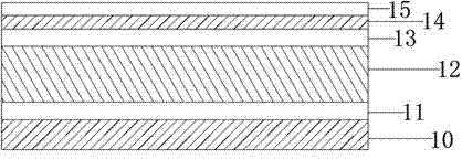
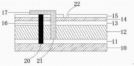
[0029] figure 1 It is a structural schematic diagram of the flexible PI substrate copper indium gallium selenium thin film battery described in the present invention; figure 2 The schematic diagram of the integrated assembly of the laser etching monomer of the flexible PI substrate copper indium gallium selenium thin film battery manufactured by the method of the present invention is provided, as figure 2 As shown, the battery includes a PI substrate 10, a back electrode 11, an absorber layer 12, a buffer layer 13, a ZnO high resistance layer 14, a top electrode 15, and an insulating adhesive layer 16 coated in the first trench 20 arranged in sequence. , the silver paste 17 filled in the second channel 21 and covering the surface of the top electrode on one side of the first channel; and the third channel 22 arranged parallel to the first channel 20 and the second channel 21 in sequence.

[0030] According to the present invention, the manufacturing method of the battery co...

Embodiment 2

[0041] For the first scribing in the above step 5, use a picosecond laser to fix the sample as in the above step 5. The laser wavelength is also 532nm green light scribing, the repetition frequency is preferably 1000kHz, and the processing speed is preferably 700mm / s. The power is preferably 3W, the width of the first channel 20 to be scribed for the first time is preferably 50-80 μm, and the laser is used to scribe the cell from the top electrode 15 (AZO layer) to the upper surface of the PI substrate 10, and the rest of the steps are the same as in the embodiment 1.

Embodiment 3

[0043] For the second scribing in the above step 7, use a picosecond laser to fix the sample as in the above step 5, and use the CCD camera of the laser to accurately align the first channel 20 of the first laser scribing for the second scribing , the laser wavelength is also scribed with 532nm green light, the repetition frequency is preferably 1000kHz, the processing speed is preferably 1000mm / s, the laser power is preferably 2.5W, and the width of the second channel 21 for the second scribe is preferably 50~70μm, The laser scribes the cell from the top electrode 15 (AZO layer) to the upper surface of the back electrode 11 (Mo film), and the rest of the steps are the same as in Embodiment 1.


PUM


Abstract

The invention provides a method of etching a single integrated assembly on a flexible PI substrate CIGS hull cell through lasers. The method comprises the following steps: step 1, the lasers are used for etching the cell from a top electrode to the upper surface of a PI substrate to form a first channel; step 2, the first channel is coated and filed with insulating cement; step 3, the lasers are used for etching the cell from the top electrode to the upper surface of a back electrode to form a second channel; step 4, the second channel and the top electrode are coated with silver paste, and the silver paste spreads from the top of the second channel and goes beyond the top of the first channel; step 5, the lasers are used for etching the cell from the top electrode to the upper surface of a high resistance layer to form a third channel, and then intraconnection of the CIGS hull cell is completed. According to the method, intraconnection of the cell is conducted after the CIGS hull cell finishes growing, as a result, the situation that different layers of materials are required to be etched respectively after sedimentation in traditional separating type etching can be avoided, the processing efficiency of intraconnection of the cell is improved, and material cost is low.

Description

technical field [0001] The invention belongs to the technical field of photovoltaic battery new energy, and relates to an interconnection method for large-area flexible polyimide (PI) substrate copper indium gallium selenium thin film batteries. Background technique [0002] Thin-film solar cells with copper indium gallium selenide (CIGS) material as the absorbing layer have the characteristics of high photoelectric conversion efficiency and good radiation resistance, and have become one of the research hotspots in the field of photovoltaic cells. Flexible substrate copper indium gallium selenide thin film solar cells can not only open up new ground application markets, but also have strong space application prospects in space. It not only has the advantages of light weight, bendability, high mass specific power, and significantly lower launch costs, but also has good performance stability under the irradiation of high-energy particles in space. With the increase of the are...

Claims


Application Information

Patent Timeline
Patent Type & Authority Applications(China)
IPC IPC(8): H01L31/18
CPCH01L31/188Y02P70/50
Inventor 张冬冬吴敏徐传明曹章轶张德涛陈亮
Owner SHANGHAI INST OF SPACE POWER SOURCES
Why Eureka
Try Eureka