
Aeration sewage treatment pond

A sewage treatment tank and aeration technology, applied in biological water/sewage treatment, water/sludge/sewage treatment, sustainable biological treatment, etc., can solve the problem of slow biochemical reaction of sludge, lower sewage temperature, and poor sewage treatment effect and other problems to achieve the effect of improving efficiency, increasing contact area, and increasing the rate of biochemical reactions

Inactive Publication Date: 2014-03-05
LESHAN SHIFENG ENVIRONMENTAL PROTECTION TECH
View PDF5 Cites 3 Cited by
  • Summary
  • Abstract
  • Description
  • Claims
  • Application Information

AI Technical Summary

Problems solved by technology

[0004] Existing sewage treatment equipment, such as aerators, need to be placed in sewage for working treatment. However, sewage is highly corrosive, and treatment equipment operating in a corrosive environment for a long time will have a certain impact on the equipment. And when the weather is relatively cold, the temperature of the sewage will decrease accordingly. When the temperature is lower than a certain temperature, the biochemical reaction of the sludge is slow and the sewage treatment effect is poor.

Method used


Image

  • Aeration sewage treatment pond
  • Aeration sewage treatment pond

Examples


Embodiment 1

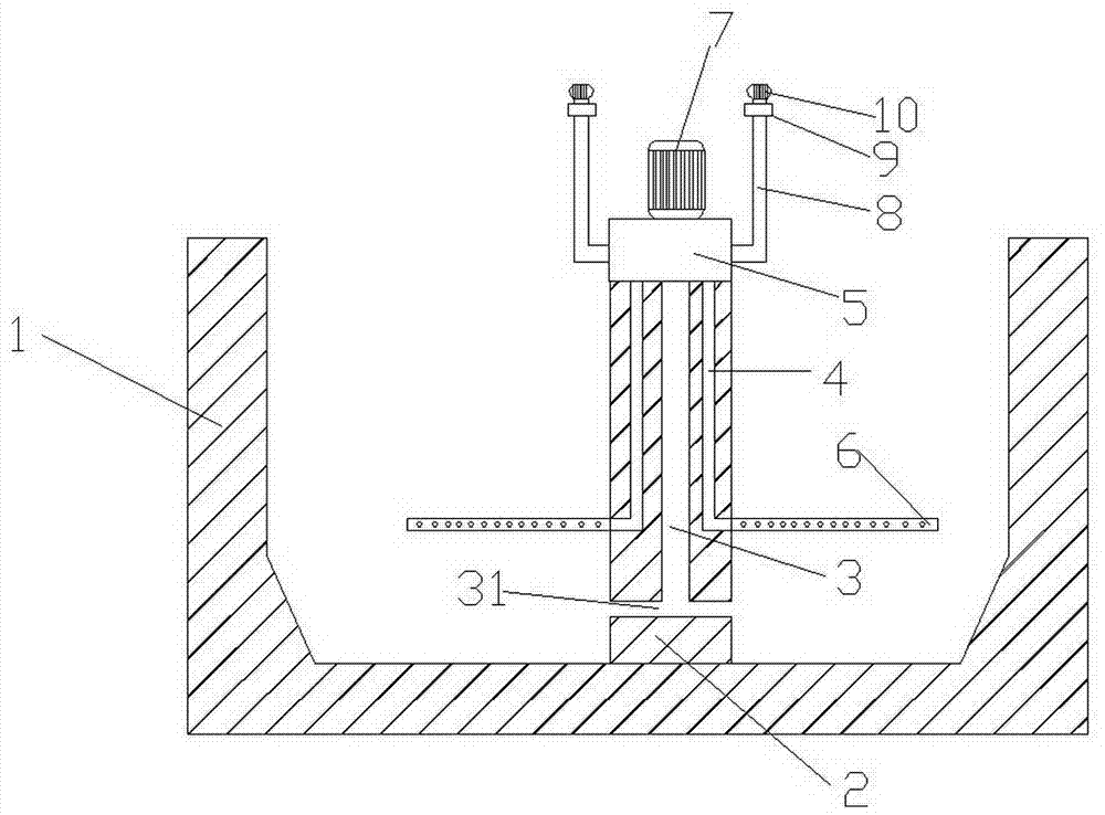
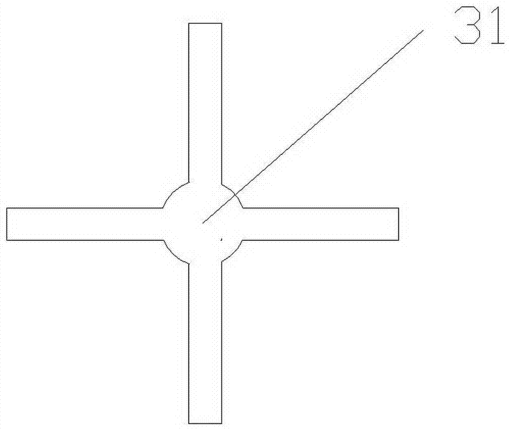
[0021] As a preferred embodiment of the present invention, with reference to the attached figure 1 , the present invention includes a sewage treatment tank 1 and an aerator, and the aerator is composed of a pumping motor, a suction pipe 8, a mixing chamber 5 and an aeration head 6; a column 2 is arranged in the sewage treatment tank 1, The column 2 is provided with a suction pipe 3 and several aeration pipes 4; the several aeration pipes 4 are arranged around the suction pipe 3; the lower end of the suction pipe 3 is provided with a multidirectional suction head 31; the aeration The head 6 is connected to the bottom of the aeration pipe 4; the multi-directional suction head 31 at the bottom of the suction pipe 3 is located below the aeration head 6; a heating device 9 is installed at the mouth of the suction pipe 8; The aeration head 6 is a long cylindrical aeration head with one end closed, and there are several aeration holes on the side wall of the aeration head 6 .

[002...

Embodiment 2

[0024] As another preferred embodiment of the present invention, with reference to the attached figure 1 , the present invention includes a sewage treatment tank 1 and an aerator, and the aerator is composed of a pumping motor, a suction pipe 8, a mixing chamber 5 and an aeration head 6; a column 2 is arranged in the sewage treatment tank 1, The column 2 is provided with a suction pipe 3 and several aeration pipes 4; the several aeration pipes 4 are arranged around the suction pipe 3; the lower end of the suction pipe 3 is provided with a multidirectional suction head 31; the aeration The head 6 is connected to the bottom of the aeration pipe 4; the multi-directional suction head 31 at the bottom of the suction pipe 3 is located below the aeration head 6; a heating device 9 is installed at the mouth of the suction pipe 8; The aeration head 6 is a long cylindrical aeration head with one end closed, and there are several aeration holes on the side wall of the aeration head 6 . ...

Embodiment 3

[0029] As the best embodiment of the present invention, with reference to the attached figure 1 , the present invention includes a sewage treatment tank 1 and an aerator, and the aerator is composed of a pumping motor, a suction pipe 8, a mixing chamber 5 and an aeration head 6; a column 2 is arranged in the sewage treatment tank 1, The column 2 is provided with a suction pipe 3 and several aeration pipes 4; the several aeration pipes 4 are arranged around the suction pipe 3; the lower end of the suction pipe 3 is provided with a multidirectional suction head 31; the aeration The head 6 is connected to the bottom of the aeration pipe 4; the multi-directional suction head 31 at the bottom of the suction pipe 3 is located below the aeration head 6; a heating device 9 is installed at the mouth of the suction pipe 8; The aeration head 6 is a long cylindrical aeration head with one end closed, and there are several aeration holes on the side wall of the aeration head 6 .

[0030] ...


PUM


Abstract

The invention discloses an aeration sewage treatment pond, and relates to the technical field of sewage treatment. The aeration sewage treatment pond disclosed by the invention comprises a sewage treatment pond body and an aerator, wherein the aerator is composed of a water pumping motor, a suction pipe, a mixing chamber and an aeration head. The aeration sewage treatment pond is characterized in that the sewage treatment pond body is internally provided with an upright column, and the upright column is internally provided with a water pumping pipeline and a plurality of aeration pipelines; the plurality of aeration pipelines are arranged on the periphery of the water pumping pipeline, the lower end of the water pumping pipeline is provided with a multi-way suction head, and the aeration heads are connected to the bottom ends of the aeration pipelines; the multi-way suction head at the bottom end of the water pumping pipeline is positioned below the aeration heads, and a pipe port of a suction pipe is provided with a heating device; the aeration heads are long cylinder type aeration heads one ends of which are sealed, and the side walls of the aeration heads are also provided with a plurality of aeration holes. The aeration sewage treatment pond disclosed by the invention has the advantages that the aeration sewage treatment pond can effectively prevent sewage from eroding aeration equipment, the normal biochemical reaction of the sludge is also guaranteed under the condition that the air temperature is reduced in cold weather, and meanwhile, a condition that the sewage is efficiently processed is guaranteed.

Description

technical field [0001] The invention relates to the technical field of sewage treatment, in particular to an aeration and sedimentation sewage treatment tank. Background technique [0002] With the development of the times and science and technology, people's living standards are improving day by day, and human beings have higher and higher requirements for the living environment. The pollution of water resources has become one of the most concerned issues of the society. A large amount of sewage discharge has further damaged the water environment. , especially some chemical companies, the sewage is directly discharged into the river without treatment, which seriously damages the environment and affects people's production and life. Therefore, the sewage treatment project is imminent. [0003] Today, with the rapid development of science and technology, there are many large, medium and small sewage treatment plants, and various sewage treatment equipment emerge in an endles...

Claims


Application Information

Patent Timeline
Patent Type & Authority Applications(China)
IPC IPC(8): C02F3/12
CPCY02W10/10
Inventor 柯玉章谢军周志玺
Owner LESHAN SHIFENG ENVIRONMENTAL PROTECTION TECH
Learn More