
Rotational flow dissolved air floatation sewage treatment equipment

A kind of sewage treatment equipment, dissolved air flotation technology, applied in the direction of flotation water/sewage treatment, centrifugal separation water/sewage treatment, etc., can solve the problem of limited treatment capacity, treatment effect, dissolved air release is disturbed by swirl, industrial application Or less inventions, etc., to achieve the effect of saving the amount of gas used for flotation, easy operation and maintenance, and reducing the number of supporting equipment

Active Publication Date: 2014-03-05
北京莱柯倍耳技术有限公司
View PDF2 Cites 4 Cited by
  • Summary
  • Abstract
  • Description
  • Claims
  • Application Information

AI Technical Summary

Problems solved by technology

[0005] Domestic related research is still in the initial stage of laboratory research, and there are few related industrial applications or inventions. Most of them are simply used in series with dissolved air flotation equipment and cyclone separation equipment, or the sewage to be treated is pressurized and dissolved in air and then enters the cyclone. flow separator separation
These technologies have disadvantages such as large power consumption, large area occupied by pressurized dissolved air tanks, easy contamination and blockage, interference of dissolved air release by swirling flow, unstable flotation effect, limited processing capacity and treatment effect, etc., which limit this type of swirling air flotation technology Carry out product application

Method used


Image

  • Rotational flow dissolved air floatation sewage treatment equipment

Examples


Embodiment 1

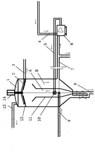
[0021] A swirling dissolved air flotation sewage treatment equipment, including: dissolved air pump 6, releaser 10, slag scraper 2, reducer 14, which is: the top dome head, the middle is a cylinder, and the longitudinal section of the lower part is V The font-shaped tank body 1 is equipped with an inner tank tube 11 whose upper end is a trumpet opening, the middle part is a cylinder, and the longitudinal section of the lower part is V-shaped with the same center line. The bottoms of the tank body 1 and the inner tank barrel 11 are respectively connected with the mud discharge pipeline 8, and the upper fitting position in the tank body 1 is welded with a slagging dome 12 with a through hole in the middle and a tapered longitudinal section; The side wall of the tank body 1 matching the lowest part of the dome 12 is connected to the slag discharge pipe 3 through a flange interface; the center of the outer top of the tank body 1 is provided with a reducer 14, and the reducer 14 is ...


PUM


Abstract

The invention discloses rotational flow dissolved air floatation sewage treatment equipment. A tank body is internally sleeved with an inner tank cylinder with the same central line; the bottom parts of the tank body and the inner tank cylinder are respectively connected with a mud discharge pipeline, wherein the adaptive part of the upper part in the tank body is provided with a residue collecting round top; the tank body side wall which is adaptive to the lowermost part of the residue collecting round top is provided with a residue discharge pipeline; the top of the tank body is provided with a tail gas pipeline; a water intake pipeline penetrates through the tank body and is connected with the adaptive part of the inner tank cylinder; a water drainage pipeline comprises a main water exhaust end opening and an end opening connected with an inlet of a dissolved air pump; the inlet of the dissolved air pump is also connected with a dissolved air source pipeline; an outlet of the air dissolved pump is connected with one end of a backflow pipeline; the other end of the backflow pipeline is connected with a releaser positioned at the adaptive part of the inner tank cylinder. The rotational flow dissolved air floatation sewage treatment equipment provided by the invention is applied to wastewater treatment for each industry, has the characteristics of high treatment efficiency, low running cost, simple structure, easiness in operation and maintenance and the like, is stable and favorable in effluent quality, is high in technology adaptability, and has good economical and social benefits.

Description

technical field [0001] The invention relates to sewage treatment equipment, in particular to a swirling dissolved air flotation sewage treatment equipment suitable for industrial and civil wastewater treatment. Background technique [0002] Industrial and civil sewage, especially petroleum refining and metallurgical sewage, usually contains oil, suspended solids, colloids, and dissolved substances, among which oil can be divided into slick oil, mechanically dispersed oil, emulsified oil, dissolved Oil and solids adhere to oil. Generally, oil is the main object of removal. While removing oil, other pollutants such as suspended solids and sewage COD can be effectively removed simultaneously. [0003] General degreasing methods include gravity degreasing, filtering degreasing, coagulation degreasing, cyclone degreasing, air flotation degreasing and other process methods. With the advancement of technology and the improvement of the country's environmental protection requirem...

Claims


Application Information

Patent Timeline
Patent Type & Authority Applications(China)
IPC IPC(8): C02F1/24C02F1/38
Inventor 王仲贤
Owner 北京莱柯倍耳技术有限公司
Learn More