A kind of anti-glare solar cell module and its preparation process
A solar cell and solar cell technology, which is applied in photovoltaic power generation, electrical components, sustainable manufacturing/processing, etc., can solve the problems of large overall mass of solar cell modules, glare and light pollution, and reduce glare effect, so as to reduce the overall weight , good light transmittance, the effect of improving the conversion efficiency
- Summary
- Abstract
- Description
- Claims
- Application Information
AI Technical Summary
Problems solved by technology
Method used
Image
Examples
Embodiment 1
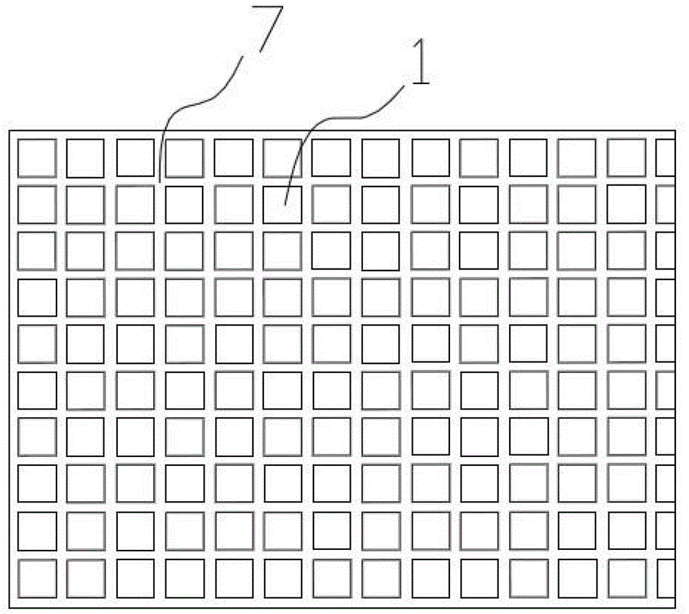
[0031] A kind of anti-glare solar cell module, comprises being arranged on the top layer, the ETFE front plate 1 that thickness is 3mm and the glass back plate 4 that is arranged on the bottom, is provided with solar cell sheet 3 between the ETFE front plate and the glass back plate, each column solar energy The cells are connected in series through welding ribbons 5 to form battery strings, and the battery strings are connected through bus bars 6 to form a solar cell matrix. Hot-melt adhesive layers 2 are provided between the ETFE front plate and the solar cells, and between the solar cells and the glass back plate. , the hot melt adhesive layer is an EVA layer, and the surface of the ETFE front plate is provided with a U-shaped scattering groove 7 with a width of 0.5mm and a depth of 0.2mm, and the interval between adjacent scattering grooves is 2mm. The criss-cross pattern is a grid structure.
[0032] A preparation process for an anti-glare solar cell module, comprising th...
Embodiment 2
[0040] A kind of anti-glare solar cell module, comprises being arranged on the top layer, the ETFE front plate 1 that thickness is 4mm and the glass back plate 4 that is arranged on the bottom, is provided with solar cell sheet 3 between ETFE front plate and glass back plate, each column solar energy The cells are connected in series through welding ribbons 5 to form battery strings, and the battery strings are connected through bus bars 6 to form a solar cell matrix. Hot-melt adhesive layers 2 are provided between the ETFE front plate and the solar cells, and between the solar cells and the glass back plate. , the hot melt adhesive layer is an EVA layer, the surface of the ETFE front plate is provided with a U-shaped scattering groove 7, the width of the scattering groove is 0.7mm, the depth is 0.3mm, and the interval between adjacent scattering grooves is 3mm. The criss-cross pattern is a grid structure.
[0041] A preparation process for an anti-glare solar cell module, com...
Embodiment 3
[0049] An anti-glare solar cell assembly, comprising an ETFE front plate 1 with a thickness of 5mm on the top layer and a glass back plate 4 arranged on the bottom layer, solar cells 3 are arranged between the ETFE front plate and the glass back plate, and each row of solar energy The cells are connected in series through welding ribbons 5 to form battery strings, and the battery strings are connected through bus bars 6 to form a solar cell matrix. Hot-melt adhesive layers 2 are provided between the ETFE front plate and the solar cells, and between the solar cells and the glass back plate. , the hot melt adhesive layer is an EVA layer, and there is a U-shaped scattering groove 7 on the surface of the ETFE front plate. The width of the scattering groove is 1mm, the depth is 0.4mm, and the interval between adjacent scattering grooves is 4mm. Cross grid structure.
[0050] A preparation process for an anti-glare solar cell module, comprising the following steps:
[0051] (a) The...
PUM
 Abstract
Description
Claims
Application Information
 - R&D Engineer
- R&D Manager
- IP Professional
- Industry Leading Data Capabilities
- Powerful AI technology
- Patent DNA Extraction
Browse by: Latest US Patents, China's latest patents, Technical Efficacy Thesaurus, Application Domain, Technology Topic, Popular Technical Reports.
© 2024 PatSnap. All rights reserved.Legal|Privacy policy|Modern Slavery Act Transparency Statement|Sitemap|About US| Contact US: help@patsnap.com


