
Sludge conditioning system and sludge conditioning method

A sludge conditioning and sludge technology, applied in sludge treatment, chemical instruments and methods, water/sludge/sewage treatment, etc., can solve the problems of less carbon source, high treatment cost and low treatment efficiency in sewage plants , to achieve the effect of reducing anaerobic digestion time, increasing methane gas production, and wide application range

Active Publication Date: 2014-02-19
TIANJIN CARING TECH DEV
View PDF5 Cites 2 Cited by
  • Summary
  • Abstract
  • Description
  • Claims
  • Application Information

AI Technical Summary

Problems solved by technology

[0002] Activated sludge method is currently the most widely used sewage biological treatment technology in China, but this method has some problems in the operation of urban sewage plants: 1. Some sewage plants have less carbon sources, resulting in poor biodegradability of sewage and low treatment efficiency; 2. Activated sludge contains a large number of microbial groups, resulting in high moisture content and large volume of mud cake during the sludge dewatering process, which takes up a lot of operating costs and land resources for landfill; 3. Anaerobic sludge treatment The digestion process has the disadvantages of slow reaction speed, too long residence time of sludge in the tank, and large tank volume.
In engineering applications, the traditional treatment process has problems such as difficult engineering, high treatment cost, high energy consumption, low efficiency, easy clogging, and low efficiency of sludge cell wall breaking. Therefore, according to actual needs, a new type of sludge cell wall breaking is developed. Refining and tempering technology is still the key research direction in the future

Method used


Image

  • Sludge conditioning system and sludge conditioning method
  • Sludge conditioning system and sludge conditioning method
  • Sludge conditioning system and sludge conditioning method

Examples


Embodiment 1

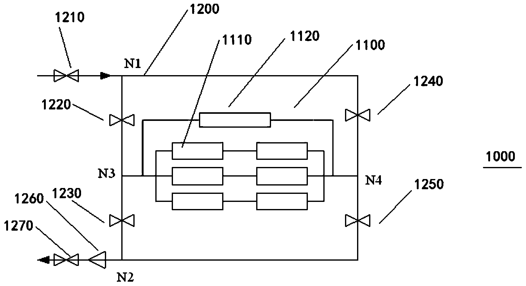
[0073] according to figure 1 The sludge conditioning system 1000 shown in one embodiment of the present invention includes: a pretreatment pipeline 1100, the pretreatment pipeline 1100 includes one or more pretreatment pipeline units 1110 and a high-voltage electric field generating device 1120; anti-clogging The pipeline 1200 forms a bridge pipeline together with the pretreatment pipeline 1100, so that the pretreatment pipeline 1100 can flow in both forward and reverse directions, thereby effectively reducing sludge clogging.

[0074] according to figure 1 Shown is a sludge conditioning system 1000 according to an embodiment of the present invention, wherein the anti-clogging pipeline 1200 includes an inlet valve 1210, an outlet valve 1270, and a first control valve 1220, a second control valve 1230, and a third control valve 1240 and the fourth control valve 1250, wherein the series pipeline formed by the first control valve 1220 and the second control valve 1230 and the se...

Embodiment 2

[0085] according to figure 1 The sludge conditioning system 1000 shown in one embodiment of the present invention includes: a pretreatment pipeline 1100, the pretreatment pipeline 1100 includes one or more pretreatment pipeline units 1110 and a high-voltage electric field generating device 1120; anti-clogging The pipeline 1200 forms a bridge pipeline together with the pretreatment pipeline 1100, so that the pretreatment pipeline 1100 can flow in both forward and reverse directions, thereby effectively reducing sludge clogging.

[0086] according to figure 1 Shown is a sludge conditioning system 1000 according to an embodiment of the present invention, wherein the anti-clogging pipeline 1200 includes an inlet valve 1210, an outlet valve 1270, and a first control valve 1220, a second control valve 1230, and a third control valve 1240 and the fourth control valve 1250, wherein the series pipeline formed by the first control valve 1220 and the second control valve 1230 and the se...

Embodiment 3

[0096] according to figure 1 The sludge conditioning system 1000 shown in one embodiment of the present invention includes: a pretreatment pipeline 1100, the pretreatment pipeline 1100 includes one or more pretreatment pipeline units 1110 and a high-voltage electric field generating device 1120; anti-clogging The pipeline 1200 forms a bridge pipeline together with the pretreatment pipeline 1100, so that the pretreatment pipeline 1100 can flow in both forward and reverse directions, thereby effectively reducing sludge clogging.

[0097] according to figure 1 Shown is a sludge conditioning system 1000 according to an embodiment of the present invention, wherein the anti-clogging pipeline 1200 includes an inlet valve 1210, an outlet valve 1270, and a first control valve 1220, a second control valve 1230, and a third control valve 1240 and the fourth control valve 1250, wherein the series pipeline formed by the first control valve 1220 and the second control valve 1230 and the se...


PUM


Abstract

The invention discloses a sludge conditioning system. The sludge conditioning system comprises a preprocessing pipeline which comprises one or more preprocessing pipeline units and a high-voltage electric field generating device, wherein the high-voltage electric field generating device comprises electrode bars coaxial with the preprocessing pipeline units, high-voltage generating modules for forming high-voltage variable electric fields in the preprocessing pipeline units, and voltage control modules, the first ends of the voltage control modules are connected with the high-voltage generating modules, the second ends of the voltage control modules are connected with the electrode bars and the voltage control modules are used for controlling the frequency and the amplitude of high voltage generated by the high-voltage generating modules; the sludge conditioning system further comprises blockage preventing pipelines; the blockage preventing pipelines and the preprocessing pipelines form bridge pipelines together, so that the preprocessing pipelines can flow in the positive direction and the negative position to effectively reduce the sludge blockage. The invention further discloses a sludge conditioning method using the sludge conditioning system. The sludge conditioning system disclosed by the invention is used for sludge conditioning, so that the pipelines are difficult to block, and the wall-broken rate is high.

Description

technical field [0001] The invention relates to the field of sludge treatment, in particular to a sludge conditioning system and a conditioning method thereof. Background technique [0002] Activated sludge method is currently the most widely used sewage biological treatment technology in China, but there are some problems in the operation of urban sewage plants in this method: 1. Some sewage plants have less carbon sources, resulting in poor biodegradability of sewage and low treatment efficiency; 2. Activated sludge contains a large number of microbial groups, resulting in high moisture content and large volume of mud cake during the sludge dewatering process, which takes up a lot of operating costs and land resources for landfill; 3. Anaerobic sludge treatment The digestion process has disadvantages such as slow reaction speed, too long residence time of sludge in the tank, and large tank volume. [0003] It can be seen that certain pretreatment of sludge can promote cel...

Claims


Application Information

Patent Timeline
Patent Type & Authority Applications(China)
IPC IPC(8): C02F11/00
Inventor 李玉庆张建刘范嘉
Owner TIANJIN CARING TECH DEV
Learn More