Machining method for forming holes in peripheral surface of housing of timing gear and special combination drilling machine for machining method

A combined drilling machine and gear chamber technology, applied in the field of mechanical parts processing, can solve the problems of difficulty in ensuring accuracy, different positioning references, and low processing efficiency, so as to avoid errors, ensure position accuracy, and improve processing quality.

Active Publication Date: 2014-02-19
杭州德曼汽车零部件有限公司
View PDF8 Cites 11 Cited by
  • Summary
  • Abstract
  • Description
  • Claims
  • Application Information

AI Technical Summary

Problems solved by technology

CN102240885A discloses a processing method of a timing gear chamber. When processing the mounting hole on the peripheral surface of the timing gear chamber, the processing steps include: (10) drilling the top surface hole of the gear chamber; (11) drilling and tapping the gear chamber (12) secondary drilling, chamfering, and tapping of the side hole of the gear chamber; this processing method is used for the mounting holes on the peripheral surface of the gear chamber, using traditional sequential drilling, and the accuracy is difficult Guaranteed, and less efficient
Generally, the mounting holes on the five outer peripheral surfaces of the timing gear chamber need to be processed, and most of these mounting holes are threaded holes. Such sequential processing not only has different positioning references, but also has low precision; moreover, drills and taps need to be replaced. Processing efficiency is very low

Method used


Image

  • Machining method for forming holes in peripheral surface of housing of timing gear and special combination drilling machine for machining method
  • Machining method for forming holes in peripheral surface of housing of timing gear and special combination drilling machine for machining method
  • Machining method for forming holes in peripheral surface of housing of timing gear and special combination drilling machine for machining method

Examples


Embodiment 1

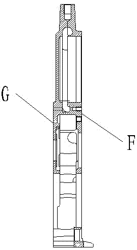
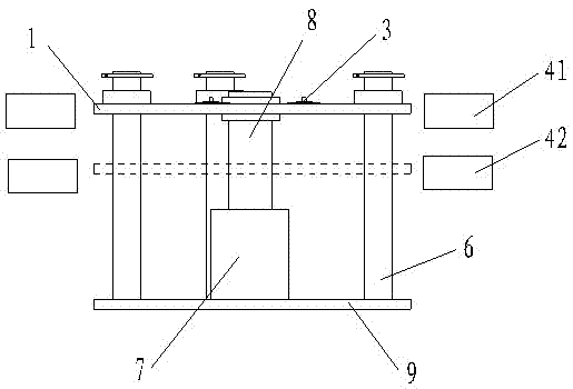
[0022] Embodiment 1: with reference to attached figure 2 , 3 , with processing attached figure 1 Take the timing gear chamber shown in as an example. A special combination drilling machine for processing the peripheral surface of a timing gear chamber, comprising a workpiece clamping table 1 installed in the drilling machine; An oil cylinder 7 is arranged between them; the bottom of the oil cylinder 7 is fixed on the machine tool base plate 9, and the end of the ejector rod 8 of the oil cylinder 7 is fixed on the center of the workpiece clamping table 1; the outer circumference of the workpiece clamping table 1 is provided with four Lugs 2; four guide posts 6 are arranged between the workpiece clamping table 1 and the machine tool base plate 9; the bottom ends of the guide posts 6 are fixed on the machine tool base plate 9, and the top ends of the guide posts 6 pass through the lugs 2 And the workpiece clamping platform 1 can lift and slide on the guide column 6; the top o...

Embodiment 2

[0023] Embodiment 2: On the basis of Embodiment 1, a special combination drilling machine for processing the peripheral surface of the timing gear chamber, wherein at each processing station, a drill bit is installed in the upper multi-axis device 41, and a tap is installed in the lower multi-axis device 42 The drill bits and taps of the multi-axis device 4 are all horizontal, and the number and position of the drill bits and taps are respectively opposite to the holes on the outer peripheral surface of the timing gear chamber to be processed; the workpiece clamping platform 1 is under the action of the oil cylinder 7 When rising to the upper multiaxial device 41, the drilling operation is completed under the action of the upper multiaxial device 41; when the workpiece clamping table 1 descends to the lower multiaxial device 42 under the action of the oil cylinder 7, 42 to complete the tapping operation.

Embodiment 3

[0024] Embodiment 3: a kind of processing method of the peripheral surface of the timing gear chamber, which utilizes the special combined drilling machine for processing the peripheral surface of the timing gear chamber described in embodiment 1, comprising the following steps:

[0025]① Place the timing gear chamber on the workpiece clamping table 1, and the positioning pin 3 passes through the process positioning pin hole of the timing gear chamber;

[0026] ②Start the hydraulic chuck 5, the pressure block 52 above the hydraulic cylinder 51 descends, and press the timing gear chamber on the workpiece clamping table 1;

[0027] ③Start the oil cylinder 7 above the bottom plate 9 of the machine tool, and lift the workpiece clamping table 1 to the position of the multi-axis device 4 equipped with the drill bit;

[0028] ④ Start the motor to drive the drill bit in the multi-axis device 4 to complete the processing of the through holes on the five outer peripheral surfaces A, B, ...


PUM


Abstract

The invention relates to a machining method for forming holes in the peripheral surface of a housing of a timing gear and a special combined drilling machine for the machining method on machining. A workpiece clamping table in the special combination drilling machine is arranged on a bottom plate of a machine tool by an oil cylinder which is perpendicularly arranged in the middle of the workpiece clamping table; a plurality of hydraulic chucks and positioning pins which are symmetric to one another are arranged on the workpiece clamping table; five machining workstations are arranged surrounding the workpiece clamping table; two multi-spindle tools which are arrayed vertically and are placed horizontally are arranged on each machining workstation; drilling bits or screw taps are respectively arranged in the upper and lower multi-spindle tools; the housing of the timing gear is positioned by a combining surface and two positioning pins; four corners of the housing of the timing gear are compressed by using the hydraulic chucks; the workpiece clamping table drives the housing of the timing gear to ascend and descend; and drilling and tapping on the peripheral surface of the housing of the timing gear can be simultaneously finished under the action of the drilling bits and the screw taps of the multi-spindle tools. By using the machining method and the special combination drilling machine, the peripheral surface of the housing of the timing gear is machined, the uniformity and the accuracy of holes are guaranteed, and the product quality and the machining efficiency are effectively improved.

Description

technical field [0001] The invention relates to a processing method and equipment for mechanical parts, in particular to a processing method for the peripheral surface of a timing gear chamber installed in a diesel engine and a special combined drilling machine. Background technique [0002] The timing gear chamber is one of the most important parts of the diesel engine. It is responsible for the installation of the entire diesel engine gear transmission system, generator and other diesel engine auxiliary devices. It belongs to the A category of the engine. In order to meet the Euro IV emission standard, the processing requirements for the timing gear chamber are also relatively high, such as the processing accuracy of the fuel injection pump gear hole, the intermediate gear hole, and the crankshaft gear hole H7, and the other gear holes H8 accuracy requirements, the flatness of the bottom plane is 0.05mm , the verticality between the bottom plane and the connecting surface ...

Claims


Application Information

Patent Timeline
Patent Type & Authority Applications(China)
IPC IPC(8): B23Q3/08B23Q1/26B23B39/16B23G1/20
CPCB23P23/02B23Q1/25B23Q3/082
Inventor 王利强
Owner 杭州德曼汽车零部件有限公司
Why Eureka
Try Eureka