Synchro switch controller

A technology of synchronous switch and controller, which is applied in the direction of program control, computer control, general control system, etc. It can solve the problems of valves being susceptible to moisture deterioration, electric sparks, and increased failures, so as to reduce the insulation level of equipment and prevent serious accidents. ignition and re-breakdown, and improve the effect of voltage stability

Inactive Publication Date: 2014-02-05
宁夏天地经纬电力设备工程有限公司
View PDF5 Cites 2 Cited by
  • Summary
  • Abstract
  • Description
  • Claims
  • Application Information

AI Technical Summary

Problems solved by technology

However, adding a closing resistor increases the complexity and cost of the switch, the voltage limiting effect is unstable, the dispersion is large, and a large amount of heat is generated due to power consumption; adding a reactor will make the installation and debugging complicated, and electric sparks will appear during operation. It is easy to form an oscillating circuit and increase the noise of the system; the installation of resistance-capacity absorption equipment will generate harmonics, which will increase the probability of failure and easily become a source of harmonic pollution; while the valve plate of the arrester is easy to be affected by moisture and deteriorate, and the temperature rise will cause active loss and form heat. Crash, in severe cases, cause MOA damage or explosion, and then cause large-scale power outages
[0004] To sum up, the traditional measures currently used cannot fundamentally solve the problem, so people have proposed the phase-controlled switching technology, which is essentially based on the characteristics of different complex (such as parallel capacitor banks, overhead transmission lines, no-load transformers, etc.) , control the switch to close or open at the best phase of voltage or current, realize smooth transition without impact, and effectively weaken the transient electromagnetic effect of the switch

Method used


Image

  • Synchro switch controller
  • Synchro switch controller
  • Synchro switch controller

Examples


Embodiment Construction

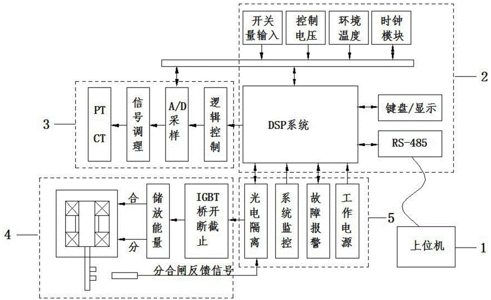
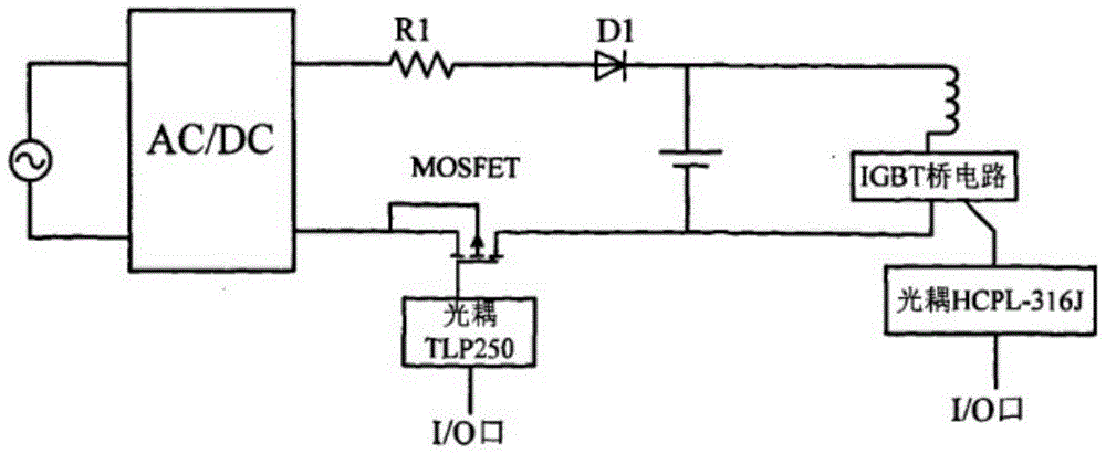
[0017] The present invention will be further described below in conjunction with the accompanying drawings. Such as figure 2 As shown, a synchronous switch controller includes a host computer communication 1, a main control module 2, a signal processing acquisition module 3, a charge and discharge control module 4 of an energy storage capacitor, and a safety interlock module 5. The main control module 2 mainly It is composed of DSP system, external RAM and man-machine interface; the signal processing acquisition module 3 is composed of analog signal conditioning, logic control and digital acquisition unit; the charge and discharge control module 4 of the energy storage capacitor is composed of AC / DC high frequency switch It is composed of power supply, discharge energy storage capacitor C, protection diode and photocoupler.

[0018] The main control module 2 judges the input information in real time, and gives a trigger signal according to a predetermined algorithm when rece...


PUM


Abstract

The invention discloses a phase selection switch controller which comprises an upper machine communication module, a main control module, a signal processing and collecting module, a charging and discharging control module of an energy storing capacitor and a safety interlocking module. The main control module is mainly composed of a DSP system, an external RAM and a man-machine interface. The signal processing and collecting module is composed of an analog signal conditioning unit, a logic control unit and a digit collecting unit. The charging and discharging control module of the energy storing capacitor is composed of an AC / DC high-frequency switch power supply, a discharging and energy storing capacitor C, a protective diode and a photoelectric coupler. The phase selection switch controller has the advantages that during closing and opening of the capacitor, inrush currents are reduced, overvoltage is hindered, a series reactor is not needed, the overhauling period and the service life of a high-voltage switch are prolonged, re-ignition and re-strike are prevented and the insulating level of equipment is lowered. When fault currents are cut off, the cut-off capability is improved, abrasion of the switch is reduced, stability of the system is improved and the service life of the switch is prolonged.

Description

technical field [0001] The invention relates to the technical field of vacuum switch controllers, in particular to a synchronous switch controller. Background technique [0002] Vacuum circuit breakers are widely used in various fields of distribution network due to their excellent performance characteristics. However, vacuum switches also have their limitations. This kind of interference will cause overvoltage and overcurrent in the power system, and even spread to the remote end to affect other users. When the capacitor bank is closed, the voltage across the contacts at the moment of closing is random. If the voltage across the contacts is not zero at this time, an inrush current with high frequency and amplitude will be generated. Theoretically, the maximum inrush current can be up to 50 times the steady state value. [0003] Traditionally, methods such as adding closing resistors, reactors, resistance-capacity absorption equipment, and using zinc oxide arresters are ge...

Claims


Application Information

Patent Timeline
IPC IPC(8): G05B19/042
Inventor 雍少银
Owner 宁夏天地经纬电力设备工程有限公司
Why Eureka
Try Eureka