Method and device for intensity compensation of differential pressure sensor

A differential pressure sensor and intensity compensation technology, applied in measuring devices, instruments, measuring fluid pressure, etc., can solve the problems of complex sensor structure, unreliable performance, large volume and quality, etc., and achieve simple optical fiber layout and simplified data processing module , The effect of simplifying the overall optical path structure

Active Publication Date: 2015-08-12
贵州智能加数字科技有限公司
View PDF8 Cites 0 Cited by
  • Summary
  • Abstract
  • Description
  • Claims
  • Application Information

AI Technical Summary

Problems solved by technology

[0008] In order to solve the problems of complex sensor structure, unreliable performance, high processing cost and large volume quality, it is proposed to adopt such a differential pressure sensing method and its sensor. The main point of this sensing method is that it is used to measure The detection fluid (such as hydraulic oil) that generates pressure from the measured object is used for sensing, so that the pressure generated by the detection fluid impacts one side of an elastic diaphragm to deform the elastic diaphragm; the other side of the elastic diaphragm is used The narrow-band laser in the incident fiber is irradiated, and the receiving fiber is used to receive the reflected light; in this way, when the elastic diaphragm is deformed, due to the change of the reflection angle, the reflected light changes accordingly, resulting in the output light intensity of the receiving fiber. In this way, the change in pressure caused by the detection fluid to the elastic diaphragm can be judged by detecting the change in the output light intensity of the receiving optical fiber

Method used


Image

  • Method and device for intensity compensation of differential pressure sensor
  • Method and device for intensity compensation of differential pressure sensor
  • Method and device for intensity compensation of differential pressure sensor

Examples


Embodiment Construction

[0046] The present invention will be further described in detail below in conjunction with the accompanying drawings and embodiments.

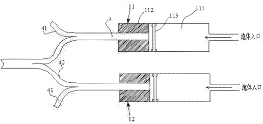
[0047] look first figure 1 , figure 1 The structural principle of the differential pressure sensor probe of the present invention is shown. As can be seen from the figure, the differential pressure sensor has two probes, namely probe one 11 and probe two 12. The structures of the two probes are exactly the same. In the probe housing 112 An elastic diaphragm 113 is arranged near the middle of the probe, and the elastic diaphragm 113 divides the interior of the probe housing 112 into two parts, one side is a detection cavity 111 and the other side is a fixing hole. The detection cavity 111 can allow the detection fluid to flow in, and the fixing hole can allow the optical fiber bundle 4 to be inserted. The optical fiber bundle 4 is processed into a bundle by 1 incident optical fiber 42 and 10 receiving optical fibers 41 (combined Figure 5 Th...


PUM


Abstract

The invention discloses a method for compensating for the intensity of a differential pressure sensor. The method is characterized in that two light sources are adopted to alternately emit light, two detection probes of the same structures are adopted to carry out detection, a Y-type coupler couples or separates light paths, then the ratios between pressure values of the two detection probes and a reference light path are calculated, and arithmetical operation is carried out on the ratios, so errors produced by fluctuation of the light sources are eliminated. The light bridge type layout mode is adopted in the light paths, the reference light paths of the two light sources pass through the Y-type coupler to reach the same photoelectric detector, reflection light receiving light paths of the two detection probes reach another photoelectric detector through the Y-type coupler, therefore, the integral light path structure of the sensor is simplified, layout of optical fibers of the light paths can be simple, meanwhile the number of the detectors is reduced, and a later data processing module is simplified. Finally, economical and reliability design is achieved.

Description

technical field [0001] The invention relates to a strength compensation method and device for a differential pressure sensor, belonging to the technical field of differential pressure sensors. Background technique [0002] Differential Pressure Sensor DPS (Differential Pressure Sensor) is a sensor used to measure the difference between two pressures, usually used to measure the pressure difference between the front and back ends of a device or component. In recent years, differential pressure sensors have been widely used in many high-precision measurement occasions such as micro-flow measurement, leak testing, clean room monitoring, environmental tightness testing, gas flow measurement, and liquid level measurement. [0003] At present, the research on differential pressure sensors at home and abroad mainly focuses on the traditional piezoresistive differential pressure sensors and capacitive differential pressure sensors. The piezoresistive differential pressure sensor ha...

Claims


Application Information

Patent Timeline
Patent Type & Authority Patents(China)
IPC IPC(8): G01L13/00
Inventor 胡浩钟丽琼周潜张大斌曹阳
Owner 贵州智能加数字科技有限公司
Why Eureka
Try Eureka