
Hydraulic test system of well control device for oil and gas fields

A hydraulic test, oil and gas field technology, applied in wellbore/well components, measurement, earthwork drilling and production, etc., can solve the problems of difficult control of the pressure test process, lack of spare parts, and less collection of pressure test information, and achieve remote rapid The effect of stepless modulation, ensuring safety and avoiding the dangerous phenomenon of overpressure

Inactive Publication Date: 2014-02-05
CHINA PETROLEUM & CHEM CORP +1
View PDF6 Cites 7 Cited by
  • Summary
  • Abstract
  • Description
  • Claims
  • Application Information

AI Technical Summary

Problems solved by technology

Before the present invention, the pressure test flange blocking plate and the well control device were all connected by bolts, and the manual assembly and disassembly of the pressure test flange was not only cumbersome, time-consuming and labor-intensive, but also failed to meet the requirements due to uneven force on the bolts. Some sealing effect, leading to test failure
[0005] 2. The measuring instrument adopts a mechanical meter, which has a low level of accuracy and requires manual on-site reading of the measurement data. There are reading errors and the accuracy of the measurement value is low; and only the measurement value at the time of reading can be recorded, and continuous measurement parameters cannot be obtained, so it cannot reflect The change process of the measurement parameters brings difficulties to the control of the pressure test process
[0006] 3. The pressure test water pump includes irrigation pump, electric pressure test pump and pneumatic pressure test pump. When the test pressure value is close to the test pressure value, the pneumatic pressure test pump is used to supplement the water pressure until the test pressure value is reached; since the electric pressure test pump is a large-displacement high-pressure water pump, it is very difficult to control the speed of the water pressure gradually approaching the test pressure value, and it is easy to appear There is a great potential safety hazard in the case of overpressure
[0007] 4. According to the SY / 5053-2000 pressure test standard, the test object should be divided into several pressure sections for constant pressure test, that is, the stepped constant pressure test method. The existing pressure test system cannot meet the requirements of this standard
[0008] 5. Some test objects have hydraulic devices, such as hydraulic blowout preventers. When performing hydraulic tests, these hydraulic devices need to be activated. For different test objects, the oil pressure of the hydraulic device may be different, and the existing pressure test system The hydraulic source can only provide oil pressure of one pressure level, which cannot meet the needs of the test
[0009] 6. The existing pressure testing system has a single function and can only test a specific well control device, which is not universal. However, there are many types of well control devices, such as blowout preventers, manifolds, etc., and similar devices have Various structures or specifications
[0010] 7. The detection circuit and control circuit use ordinary analog circuits, which have a low level of automation and low test efficiency. It is impossible to obtain continuous real-time test data curves, and it is also inconvenient to display, record and save
[0013] 1. The hydraulic clamp can only be used for the pressure test of one size of BOP, and the scope of application is narrow;
[0014] 2. Since the pressure test system directly uses a single-channel primary instrument to display the pressure test pressure of the blowout preventer, and uses a disc-type paper recorder to record the pressure test pressure, it is necessary to introduce the high-pressure source into the console operation area, and there is a certain Potential safety hazards, and the small amount of pressure test information collection, low pressure display and recording accuracy, it is difficult to meet the use requirements;
[0015] 3. The pressure test system and process are still controlled manually, with a low degree of automation;
[0016] 4. The pressure test monitoring system uses a fixed-focus black-and-white camera and a small-screen monitor to monitor the pressure test process. The monitoring effect is poor and it is difficult to meet the monitoring requirements;
[0017] 5. The pressure test system cannot complete the storage and management of pressure test information and the generation and printout of pressure test result reports
[0018] In addition, due to the high purchase cost of the pressure test system and the lack of spare parts, the maintenance cost is relatively high

Method used

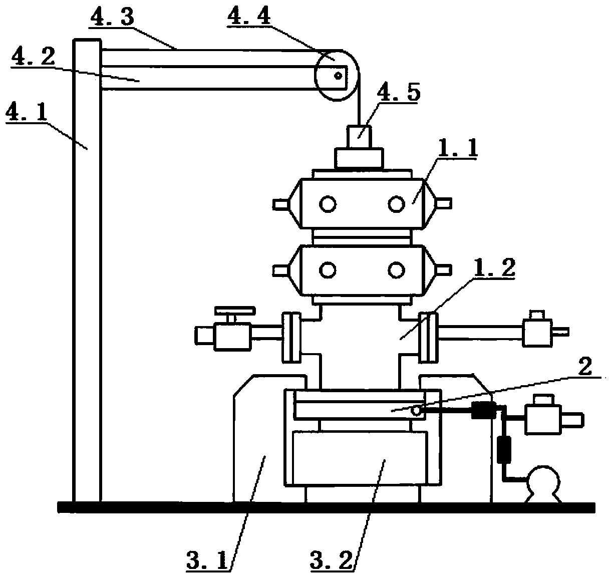
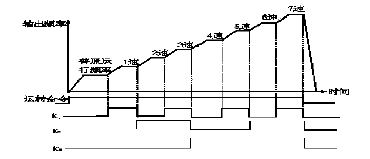

Image

  • Hydraulic test system of well control device for oil and gas fields
  • Hydraulic test system of well control device for oil and gas fields
  • Hydraulic test system of well control device for oil and gas fields

Examples


Embodiment Construction

[0048] Main research content of the present invention

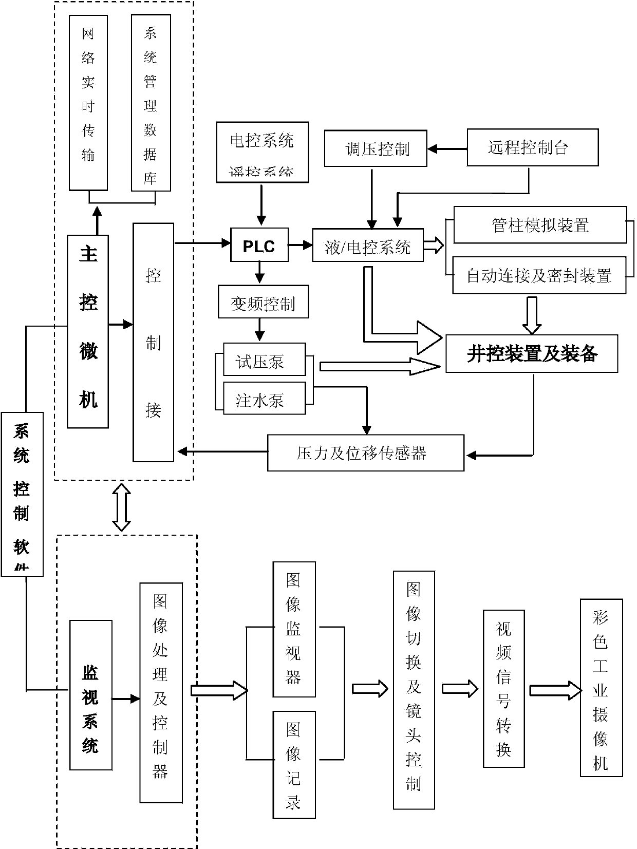
[0049] a. The index formulation and overall scheme design of the overall technology of the well control equipment pressure test monitoring and automatic data acquisition system. Aiming at the deficiencies and defects of similar systems at home and abroad, as well as the purpose and content of pressure testing of well control devices, design the technical indicators of the system and the overall plan for realizing the indicators.

[0050] b. Design of pressure test monitoring and monitoring control system. The safety of the pressure test process is very important. Since the ultra-high pressure in the pressure test process does not allow operators to approach, one of the research purposes of this project is to design all-round, whole-process remote monitoring and control, so that the pressure test process can realize remote visual monitoring and key image recording. Ensure the safety of personnel during the pressure test....


PUM


Abstract

A hydraulic test system of a well control device for oil and gas fields comprises a hydraulic test device and a control device of the hydraulic test device. The hydraulic test device comprises a pressure test pump unit, a pressure test flange block board and a pressure release valve, wherein the pressure test pump unit is used for pumping test water into the to-be-tested well control device through a pipeline, the pressure test flange block board is in butt joint with a lower port flange of the to-be-tested well control device and used for entrapping the to-be-tested well control device, so that an enclosure space is formed inside the to-be-tested well control device, and the pressure release valve is used for releasing the hydraulic pressure of the to-be-tested well control device. The hydraulic test system is characterized by further comprising a pressure test flange block board clamping mechanism for clamping the pressure test flange block board and the lower port flange of the to-be-tested well control device and sealing butt joint surfaces of the two flanges; and the control device comprises a water filling pump process control module, a pressure test flange block board clamping mechanism process control module, a water storage tank liquid level control module, a hydraulic oil pressure control module and a pressure release valve process control module. The system is high in automation level and test efficiency, complete in function and capable of meeting test requirements for various wellhead devices and accords with a SY / 5053-2000 pressure test standard, the whole test process is remotely operated and monitored, and testers are not required to be on the spot.

Description

technical field [0001] The invention relates to a hydraulic test system for a well control device in an oil and gas field, and belongs to the technical field of testing. Background technique [0002] In the process of oil and gas drilling, the well control device is an important facility to control the high-pressure oil and gas flow in the well, and it is an important guarantee to ensure the safe and smooth implementation of the drilling and development process. Well control device refers to the general designation of special equipment and tools required for the implementation of oil and gas well pressure control technology, mainly blowout preventers. The specification stipulates that before any well control device is put into use, strict pressure test and water / air pressure sealing test must be carried out to ensure that the well control device can reliably and effectively control the high-pressure oil and gas flow in the well in actual use and prevent blowout accidents . ...

Claims


Application Information

Patent Timeline
IPC IPC(8): E21B47/00
Inventor 杨勇吕玉胜王勋彭兵粟建辉杨军方晓庆钟成千
Owner CHINA PETROLEUM & CHEM CORP
Learn More