
Heat cooling apparatus assembly of LED illuminating device having heat pipe and heat sink

A technology for LED lighting and cooling devices, applied in entertainment and other directions, can solve the problems of unsuitable LED lighting fixtures, the size or weight of cooling devices, etc., to maximize heat dissipation efficiency, improve heat dissipation effect, and reduce weight.

Inactive Publication Date: 2014-01-29
(株)日星
View PDF12 Cites 0 Cited by
  • Summary
  • Abstract
  • Description
  • Claims
  • Application Information

AI Technical Summary

Problems solved by technology

[0014] In the above-mentioned prior art, the heat pipe (10) is combined with the LED combination (20) by welding or the like, but in terms of this cooling device, compared with the size of the LED lighting fixture, the overall size or weight of the cooling device is too large. Large, unsuitable as a cooling device for relatively large LED luminaires, i.e. for high-intensity luminaires

Method used


Image

  • Heat cooling apparatus assembly of LED illuminating device having heat pipe and heat sink
  • Heat cooling apparatus assembly of LED illuminating device having heat pipe and heat sink
  • Heat cooling apparatus assembly of LED illuminating device having heat pipe and heat sink

Examples


Embodiment Construction

[0043] The following describes in detail with reference to the accompanying drawings of the present invention.

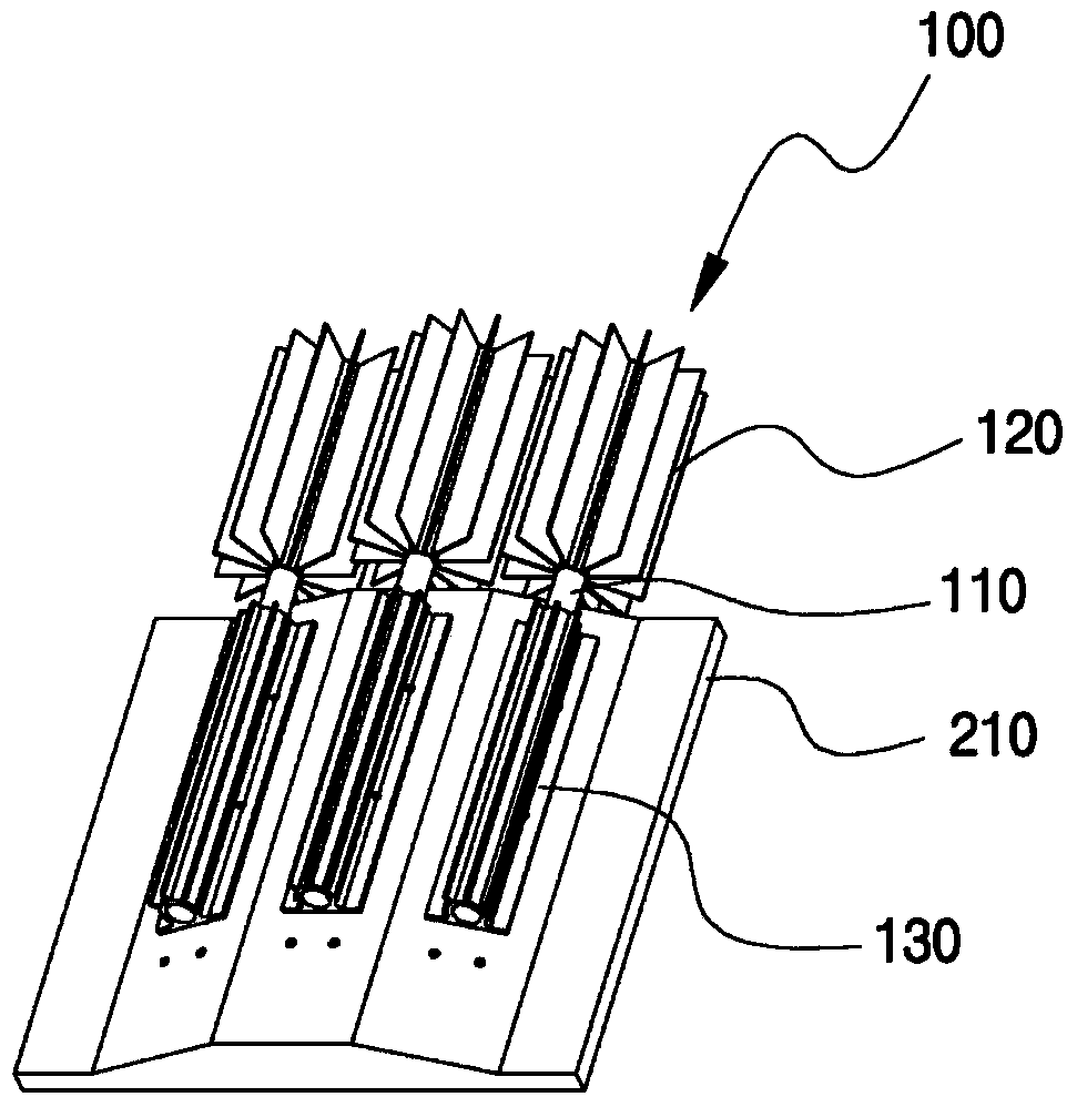
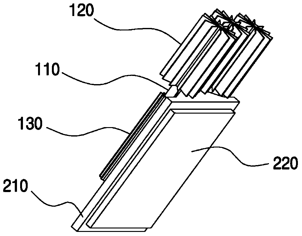
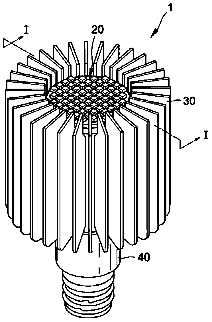
[0044] Figure 6 It is a figure which specifically illustrates the heat conduction pipe of this invention, Figure 7 and Figure 8 According to a preferred embodiment of the present invention, it is a diagram illustrating a state in which a heat pipe (400) of a cooling device for LED lighting fixtures is connected vertically rearward to an attachment plate (300) of the LED lighting fixtures.

[0045] Such as Figure 5 As shown, the main components of the cooling device for LED lighting fixtures of the present invention are composed of a disc-shaped lighting fixture installation plate (300), a heat pipe (400) and a radiator (500), wherein the heat pipe (400 ) is fixed on the side opposite to the surface on which the lighting fixture is fixed on the mounting plate, and the heat sink (500) is mechanically press-attached and fixed on the outside of the heat pipe (400...


PUM


Abstract

The invention provides a heat cooling apparatus assembly of an LED illuminating device having a heat pipe and a heat sink. The heat cooling apparatus assembly of the LED illuminating device is composed of an LED illuminating device mounting plate (300), a heat pipe (400) and a heat radiator (500). The heat pipe (400) is fixed on the opposite face of the fixed face of the illuminating device on the mounting plate. The heat radiator (500) is fixed on the outer side of the heat pipe (400) in a mechanical pressing attachment way. The apparatus is characterized in that more than one fixing hole (320) is fixed on the LED illuminating device. The heat pipe (400)is fixed towards the rear part of the mounting plate in a perpendicular way through a bonding bolt (310). One side end of the heat pipe (400) is composed of an adherence pipe (441) and an inner side pipe (442). The adherence pipe is located on the inner side of the heat pipe made in way to have a circumferential curved part (451) on the circumference. The inner side pipe (442) is inserted into the adherence pipe (441) in a pressurizing way to form screw threads (410) so that the bonding bolt (310) can be fixed inside the adherence pipe (441). The other side end of the heat pipe (400) is composed of an adherence pipe (446) and an inner side pipe (445).

Description

technical field [0001] The present invention relates to a cooling device for an LED lighting fixture having a cooling device using a heat pipe, and more specifically, to an LED lighting fixture cooling device assembly for effectively cooling heat generated by an LED using a heat pipe. Background technique [0002] LED (Light Emitting Diode, Light Emitting Diode) is a type of semiconductor and utilizes a phenomenon in which electric energy is converted into light energy to emit light when a voltage is applied. Compared with conventional fluorescent lamps or incandescent lamps, lighting fixtures using such LEDs have the advantages of not only consuming very little power, but also having high energy efficiency, having a long life, and being able to display light of various colors. However, in the LED lighting fixtures currently used, there is a problem that it is necessary to effectively cool the high heat generated by the LEDs at the time of startup. The following prior art r...

Claims


Application Information

Patent Timeline
IPC IPC(8): A99Z99/00
Inventor 李元范
Owner (株)日星
Learn More