
White-light LED manufacturing method

A technology of LED packaging and LED chips, applied in semiconductor devices, electrical components, circuits, etc., can solve the problems of blue LED peak wavelength shift, white LED color area change and other problems, achieve a large wavelength range, reduce binning, and reduce production costs Effect

Inactive Publication Date: 2014-01-29
GUANGZHOU RES INST OF NON FERROUS METALS
View PDF5 Cites 11 Cited by
  • Summary
  • Abstract
  • Description
  • Claims
  • Application Information

AI Technical Summary

Problems solved by technology

None of the above solutions can fundamentally solve the problem. As the operating temperature of the blue LED chip changes, the peak wavelength of the blue LED will drift, and the color region of the final synthesized white LED will still change.

Method used


Image

  • White-light LED manufacturing method
  • White-light LED manufacturing method
  • White-light LED manufacturing method

Examples


Embodiment 1

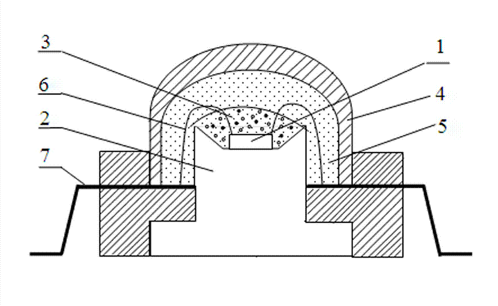
[0029] 1. Place blue LED chips 1 with excitation wavelengths of 450, 460 and 465 nm respectively on the holder cup 2 .

[0030] 2. Connect the positive and negative poles of the chip to the external positive and negative poles 7 through wires 6 respectively.

[0031] 3. Use a centrifugal mixer to mix the YAG:Ce yellow phosphor that is excited to produce 560nm yellow light, and the (Sr, Ba) that is stimulated to produce 600nm orange light. 3 SiO 5 : The phosphor glue 3 composed of Eu orange phosphor and two-component LED packaging silica gel is uniformly mixed; the mass ratio of yellow phosphor: orange phosphor: OE-6550 is 36:4:200.

[0032] 4. Evenly fill the bracket cup body 2 with phosphor glue 3, bake at 150° C., and bake for 1.5 hours.

[0033] 5. Cover the lens 4 and fill it with two-component LED packaging silicone 5 K-5505H.

[0034] 6. Bake at 150°C for 1.5 hours to shape.

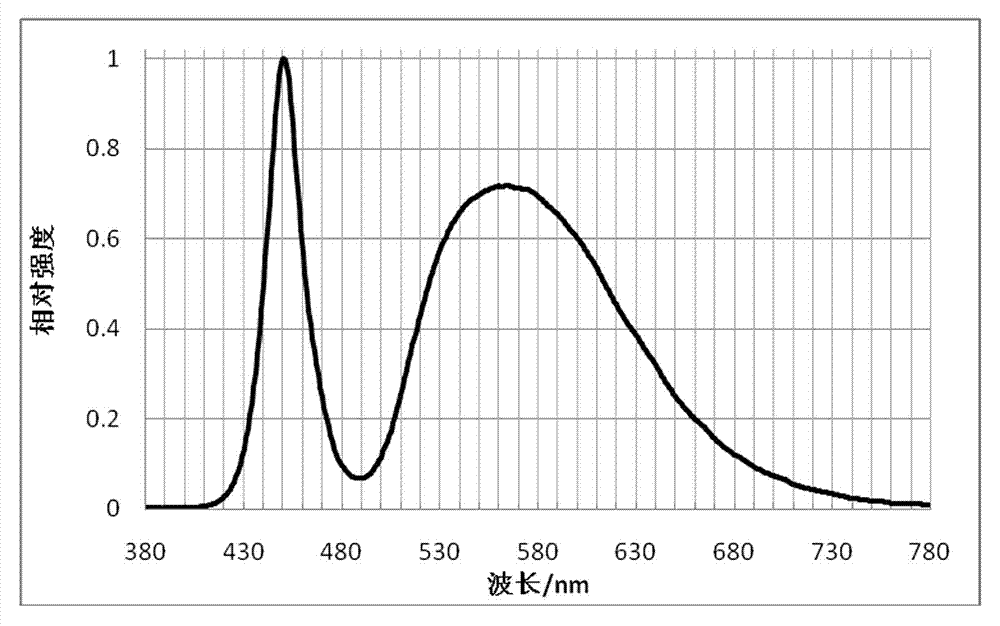
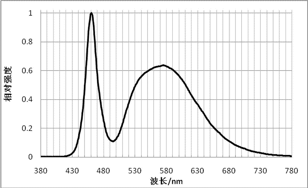
[0035] Prepared white LED figure 1 shown. When working, the blue light LED chip 1 with a ...

Embodiment 2

[0038] With embodiment 1. Phosphor powder glue 3 is composed of YAG:Ce yellow phosphor that is stimulated to produce 560nm yellow light, and (Sr,Ba) that is stimulated to produce 600nm orange light 3 SiO 5 : Eu orange phosphor, stimulated to produce 540nm yellow-green light (Y, Lu) 3 Al 5 o 12 :Ce yellow-green phosphor and Sr excited to produce 615nm red light 2 Si 5 N 8: Eu red phosphor and 5561S are evenly mixed; the mass ratio of yellow phosphor: orange phosphor: yellow-green phosphor: red phosphor: 5561S is 35:4:6:3:200.

[0039] Prepared white LED figure 1 shown. When working, blue light LED chip 1 with discrete wavelength of 450-470nm emits blue light, excites yellow phosphor to produce 560nm yellow light, excites orange phosphor to produce 600nm orange light, excites yellow-green phosphor to produce 540nm yellow-green light, and excites red fluorescence The powder produces red light at 615nm, which is mixed with the remaining blue light and emitted as white lig...


PUM


Abstract

Disclosed is a white-light LED manufacturing method. The method is characterized by including the following steps: placing a blue-light LED chip (1) with excitation wavelength of 450-470nm on a support cup body (2); electrically connecting anode and cathode of the chip with an anode and a cathode (7) which are externally connected through guide lines (6) respectively; uniformly mixing fluorescent power glue (3) formed by fluorescent power and two-component LED encapsulating silica gel, wherein mass ratio of the fluorescent power and the two-component LED encapsulating silica gel is 30-55:200; uniformly filling the support cup body (2) with the fluorescent powder glue (3), wherein baking temperature is 140-160 DEG C and baking time is 1-2 hours; covering a lens (4), and filling the two-component LED encapsulating silica gel (5); baking at 140-160 DEG C for 1-2 hours for forming. A white-light LED manufactured by the method changes along with working temperature of the blue-light LED chip, white-light color area of the white-light LED does not drift basically, and grading of the blue-light LED chip and grading of the white-light LED after being encapsulated are reduced, so that production cost is lowered.

Description

technical field [0001] The invention relates to an LED (light-emitting diode) and a preparation method thereof, in particular to a preparation method of a high-brightness, high-quality white light LED. Background technique [0002] LED semiconductor lighting is another revolution in lighting sources after incandescent lamps and fluorescent lamps. As a new type of high-efficiency solid-state light source, LED has the advantages of energy saving, environmental protection, long life, small size, and various usage methods in principle. In recent years, LED semiconductor lighting technology has developed rapidly and has a wide range of applications. [0003] The existing white light LED preparation method mainly uses blue light LED chips to mix with phosphor powder that emits yellow light after being irradiated by blue light to form a white light LED. This technology was mainly proposed by Japanese Nichia Chemical Industry Co., Ltd. in WO1998005078 (CN1268250A) published on Feb...

Claims


Application Information

Patent Timeline
Patent Type & Authority Applications(China)
IPC IPC(8): H01L33/50
CPCH01L33/005H01L33/504H01L2224/8592H01L2224/48247
Inventor 许毅钦李炳乾赵维张康刘晓燕王君君范广涵古志良
Owner GUANGZHOU RES INST OF NON FERROUS METALS
Learn More