
Injectors for cylinder lubricating oil distribution systems for large diesel engine cylinders

A diesel engine and fuel injector technology, applied in the direction of engine lubrication, engine components, machines/engines, etc., can solve the problems of unsuitable needle valves, different oil volumes, large gaps, etc., and achieve the effect of less maintenance

Active Publication Date: 2016-04-20
HANS JENSEN LUBRICATORS
View PDF9 Cites 0 Cited by
  • Summary
  • Abstract
  • Description
  • Claims
  • Application Information

AI Technical Summary

Problems solved by technology

This design has the following disadvantages: In order to avoid different oil volumes delivered to each valve, there is a higher requirement for the consistency of flow and viscosity conditions in the oil supply pipe
To prevent potentially contaminated oil from clogging / clogging the gap between the needle and the guide pin hole, a large gap is required, and since the larger gap makes the needle valve unsuitable, a new type of valve body and seat is required

Method used


Image

  • Injectors for cylinder lubricating oil distribution systems for large diesel engine cylinders
  • Injectors for cylinder lubricating oil distribution systems for large diesel engine cylinders
  • Injectors for cylinder lubricating oil distribution systems for large diesel engine cylinders

Examples


Embodiment Construction

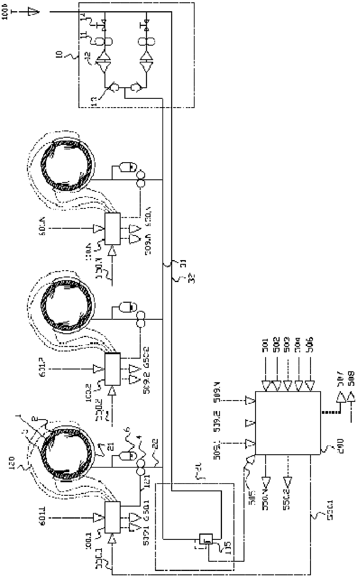
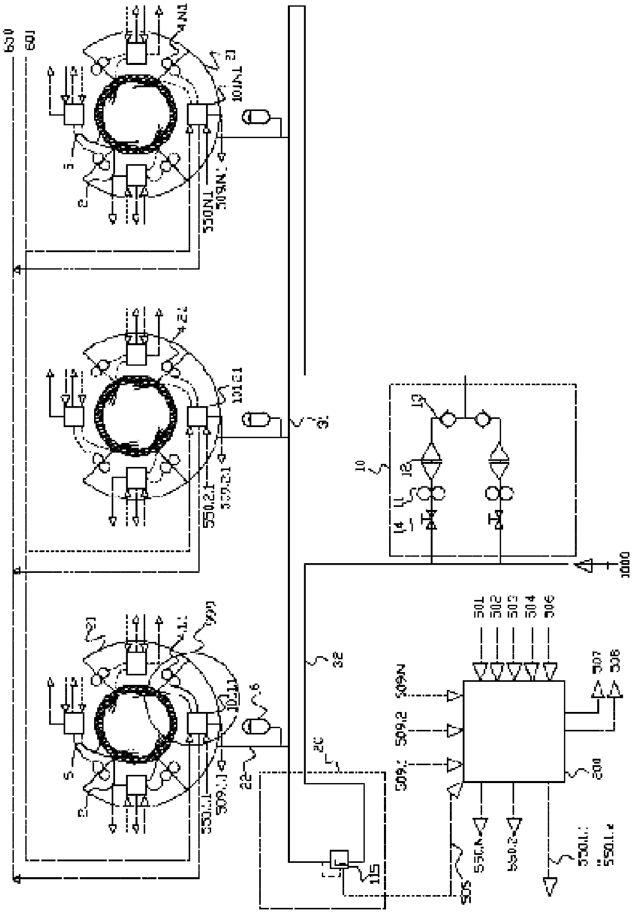
[0127] figure 1 A complete lubrication system with N cylinders 1 is shown. Each cylinder is equipped with several X injectors 2 connected to a common lubricating oil supply line 31 with a constant supply pressure, for example 30 to 100 bar in size. Oil supply pressure is supplied from the daily oil tank 1000 and transmitted through the hydraulic pump unit 10 .

[0128]The pumping station 10 comprises two pumps 11 , two filters 12 and two non-return valves 13 which prevent the return flow of lubricating oil through the stationary pumps 11 . The pump station also includes two shut-off valves 14 inserted into the oil supply pipe 34 so that the filter 12 can be cleaned during operation. Both pumps 11 back up each other and are automatically activated in the event of a drop in oil pressure.

[0129] The end of the fuel supply pipe 31 is provided with a boost valve 20 or a stepless electronically controlled boost valve 115 (the latter is shown in principle). Usually, the oil pre...


PUM


Abstract

The invention discloses a fuel injector for a cylinder lubricating oil distribution system in a cylinder of a large diesel engine, such as a marine engine. The fuel injector comprises: an inlet connected to an oil supply pipe, a switching valve unit and one or more The nozzle holes are used to inject the cylinder lubricating oil into the associated cylinders, and the oil supply pipe is led out from the lubricating oil supply equipment of the distribution system. The injector is characterized in that its on-off valve unit consists of a ball valve body and interacting valve seats, and that there is a gap with a width of more than 10 microns between the valve body stem and the valve guide wall of the on-off valve.

Description

technical field [0001] The present invention relates to a fuel injector for a cylinder lubricating oil distribution system in cylinders of large diesel engines, such as marine engines, the fuel injector comprising: [0002] ‐Inlet connected to the oil supply pipe leading from the lubricating oil supply equipment of the distribution system, the switching valve unit and one or more nozzle holes for injecting the cylinder lubricating oil into the associated cylinders. [0003] The invention is intended for electromagnetically controlled injectors in which the dosing is controlled by the opening time of the control valve. This differs from other lubrication systems where dosing is typically controlled by volume. When the valve has a built-in pump, the dosing amount of oil can be in atomized form, for example by direct control of the spray. In the system, the operation is mainly done through solenoid controlled valves. [0004] The injector is suitable for a cylinder lubricating...

Claims


Application Information

Patent Timeline
Patent Type & Authority Patents(China)
IPC IPC(8): F01M1/16F01M1/08
CPCF01M1/08F01M1/16F01M2001/083F01M1/14
Inventor 皮尔·比艾库
Owner HANS JENSEN LUBRICATORS
Learn More