
Mutual inductance coupling type switch magnetic resistance motor

A technology of switched reluctance motor and mutual inductance coupling, which is applied to the static parts of the magnetic circuit, the shape/style/structure of the magnetic circuit, the shape/style/structure of the winding conductor, etc. Problems such as large torque ripple and low material utilization rate can achieve the effect of increasing current utilization efficiency, small torque ripple, and less copper consumption

Inactive Publication Date: 2014-01-22
SOUTHEAST UNIV
View PDF6 Cites 6 Cited by
  • Summary
  • Abstract
  • Description
  • Claims
  • Application Information

AI Technical Summary

Problems solved by technology

The switched reluctance motor with the above-mentioned traditional winding structure adopts a centralized winding structure, and the motor works by the reluctance torque generated by the change of self-inductance. Only part of the winding is energized at each moment, and only part of the core directly participates in the conversion of electromagnetic energy, and the remaining winding and The iron core material is idle, so the utilization rate of the material is low, and the torque ripple of the motor with concentrated winding is large, which is not conducive to the smooth and stable operation of the motor drive system

Method used


Image

  • Mutual inductance coupling type switch magnetic resistance motor
  • Mutual inductance coupling type switch magnetic resistance motor
  • Mutual inductance coupling type switch magnetic resistance motor

Examples


Embodiment Construction

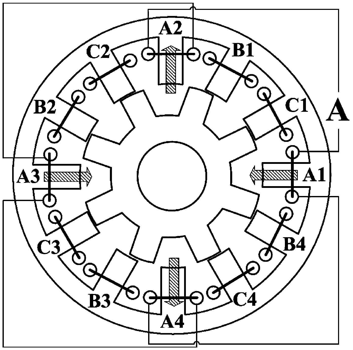
[0028] The technical solution of the present invention will be described in detail below in conjunction with the accompanying drawings.

[0029] A mutual induction coupling switched reluctance motor of the present invention comprises a stator 1 , a mutual induction coupling concentrated winding 2 and a rotor 3 . The stator 1 is provided with an even number of stator teeth, and stator slots are formed between adjacent stator teeth, and each stator tooth is opposed to another stator tooth along the radial direction of the stator. The concentrated winding coil 2 is wound on the stator teeth, which is a double-layer winding structure, nested on all the salient pole teeth of the stator 1, and two coil edges belonging to different coils are placed in each stator slot, that is, all stator teeth There are coils nested, the number of coils is equal to the number of stator teeth, and each phase winding is composed of several coils connected in series or in parallel or in series and para...


PUM


Abstract

The invention discloses a mutual inductance coupling type switch magnetic resistance motor, which is in a double-salient-pole structure, wherein salient pole teeth are respectively arranged on a stator and a rotor, but the number of the salient pole teeth on the stator and the number of the salient pole teeth on the rotor are different. An integrated winding coil is wound on the stator teeth, a multiphase symmetrical winding structure is formed, the coil adopts double-layer coil edges, i.e., two ring edges belonging to different coils are placed in each stator groove, all of the coils of the winding maintain the same winding direction, i.e. after the introduction of current in the same direction, the polarities of flux linkage of all stator poles are identical, the self inductance and the mutual inductance of each phase of winding of the motor can be periodically changed along with the position change of the rotors, i.e., the motor can work simultaneously through the reluctance torque generated through the self inductance and mutual inductance change. The invention further discloses a control method of the mutual inductance coupling type switch magnetic resistance motor. The mutual inductance coupling type switch magnetic resistance motor has the advantages that the material utilization rate of the motor can be improved, the torque pulse of the motor is effectively inhibited, and the motor control mode is more flexible and diversified.

Description

technical field [0001] The invention relates to a mutual inductance coupled switched reluctance motor. The invention belongs to the technical field of motor manufacturing and control. Background technique [0002] With the development of power electronics technology, microelectronics technology and automatic control technology, the application of switched reluctance motors is becoming more and more extensive, especially the severe price fluctuations of rare earth permanent magnet materials, so that the equipment of switched reluctance motors without permanent magnets By the attention. The traditional switched reluctance motor has a double-salient pole structure. The stator and rotor are made of laminated ordinary silicon steel sheets. There is neither permanent magnet nor winding on the rotor. There is a concentrated winding on the stator. Through the winding direction and connection method of the coil, the The mutual inductance of the motor does not change with the change...

Claims


Application Information

Patent Timeline
Patent Type & Authority Applications(China)
IPC IPC(8): H02K1/14H02K3/28
Inventor 花为华浩赵桂书程明
Owner SOUTHEAST UNIV
Learn More