
Paraxial powder-feeding working head for laser powder processing

A technology of laser powder and working head, applied in metal material coating process, coating and other directions, can solve the problems of high cladding quality, reduce powder flow rate, instability, etc., achieve precise control of powder flow rate and improve cladding quality Effect

Active Publication Date: 2014-01-22
INST OF SEMICONDUCTORS - CHINESE ACAD OF SCI
View PDF7 Cites 9 Cited by
  • Summary
  • Abstract
  • Description
  • Claims
  • Application Information

AI Technical Summary

Problems solved by technology

This method can separate the metal powder from the powder conveying gas, discharge the powder carrier gas, and reduce the flow rate of the powder ejected from the nozzle, which is beneficial to obtain high welding quality; since the side-axis powder feeding working head is generally used at an angle of 45°, so After the powder is separated from the carrier gas, some powder will accumulate at the bottom of the powder conical powder delivery tube. If this part of the accumulated powder cannot be discharged in time, the long-term powder accumulation will cause a sudden increase in powder output or block the powder delivery tube. , will affect the coating quality
In addition, since the space of the powder-air separation chamber is much larger than that of the powder feeding pipe, when the powder enters the powder feeding pipe from the powder-air separation chamber, the output of the powder will be different from that of the powder feeder, resulting in poor performance of the cladding layer. continuous, unstable

Method used


Image

  • Paraxial powder-feeding working head for laser powder processing
  • Paraxial powder-feeding working head for laser powder processing
  • Paraxial powder-feeding working head for laser powder processing

Examples


Embodiment Construction

[0027] In order to make the object, technical solution and advantages of the present invention clearer, the present invention will be further described in detail below in conjunction with specific embodiments and with reference to the accompanying drawings.

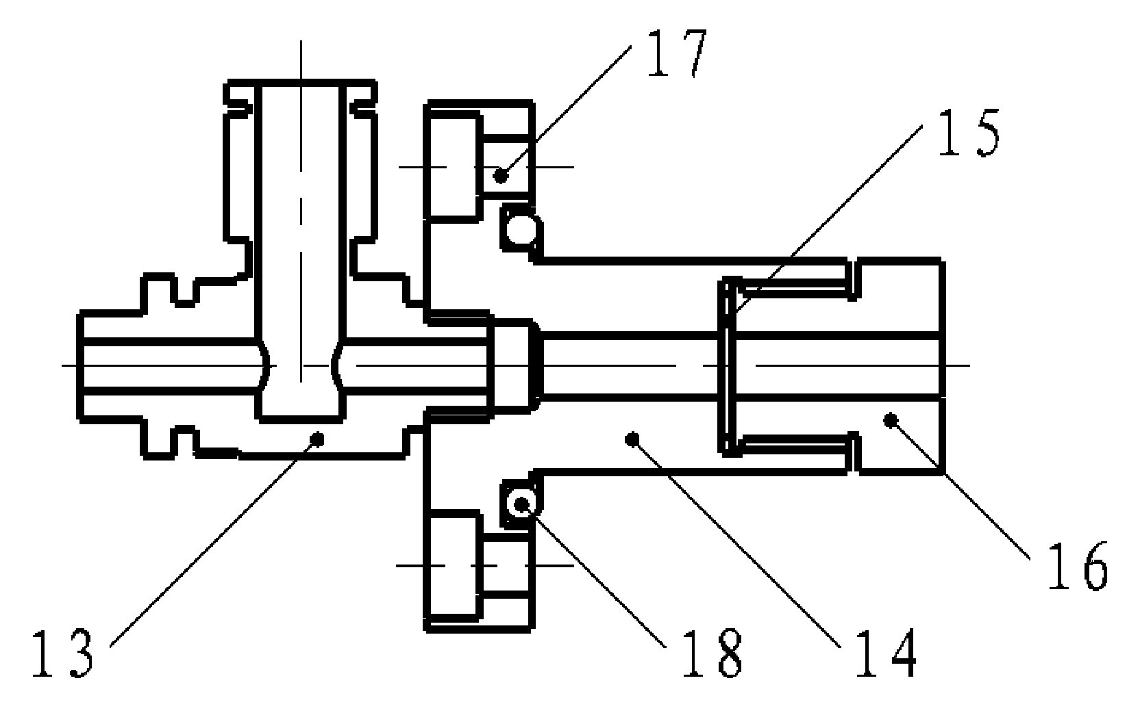
[0028] figure 1 A schematic diagram of the overall structure of the side-axis powder feeding working head for laser powder processing proposed by the present invention is shown. Such as figure 1 As shown, the working head includes a powder gas separator 1, a powder gas input chamber 2, a quick-plug connector 3, a powder converging chamber 4, a first powder conveying pipe 5, a processing gas input chamber 6, a processing gas converging part 7, a processing gas An input joint 8 , a fixing frame 9 , a second powder delivery pipe 10 , a third powder delivery pipe 11 and a powder nozzle 12 .

[0029] figure 2 A schematic structural view of the powder gas separator 1 in the present invention is shown. The powder gas separa...


PUM


Abstract

The invention relates to a paraxial powder-feeding working head for laser powder processing. The paraxial powder-feeding working head comprises a powder-gas separator, a powder-gas input chamber, a fast-plug connector, a powder collecting chamber, a first powder conveying tube, a processing gas input chamber, a processing gas collecting piece, a processing gas input joint, a fixed frame, a second powder conveying tube, a third powder conveying tube and a powder spray nozzle, wherein the processing gas collecting piece is a gradual-contraction funnel shaped component; a throttle valve is used for outputting a powder-carrying gas input by a powder feeder; a stainless steel wire net is arranged at the front end of the throttle valve. According to the paraxial powder-feeding working head disclosed by the invention, separation of metal powder and conveyed powder-carrying gas is realized, so that on one hand, outflow rate of the metal powder from the spray nozzle is lowered to ensure stability of powder conveying amount, and therefore, stable powder output amount requirements in laser powder processing processes of laser cladding, and the like are satisfied; on the other hand, a gas different from the powder-carrying gas is input from the processing gas input joint to achieve a purpose of protecting a processing piece; meanwhile, powder spraying speed of the powder feeding spray nozzle can be adjusted in an assisted manner, so that processing effect is controlled better.

Description

technical field [0001] The invention belongs to the technical field of laser processing, in particular to a side-axis powder feeding working head for laser powder processing. Background technique [0002] Laser processing has outstanding advantages such as non-contact, easy operation, high flexibility, high efficiency, high quality and energy saving. Laser cladding technology uses high-energy-density laser beam irradiation to deposit a layer of materials with special physical, chemical or mechanical properties on the surface of the matrix material through rapid melting, expansion and solidification to form a new composite material. To make up for the lack of performance of the matrix material. According to the requirements of the processed workpiece, a coating layer with heat resistance, corrosion resistance, wear resistance and other properties can be prepared, so that the material has properties that cannot be obtained by conventional treatment. [0003] Laser cladding t...

Claims


Application Information

Patent Timeline
Patent Type & Authority Applications(China)
IPC IPC(8): C23C24/10
Inventor 林学春牛奔张志研曲研南景洋周春阳
Owner INST OF SEMICONDUCTORS - CHINESE ACAD OF SCI
Learn More