A skid-mounted water injection boiler

A skid-mounted boiler technology, applied in water heaters, lighting and heating equipment, fluid heaters, etc., can solve the problems of small effective coefficient of radiation heat transfer, low-temperature corrosion of the heating surface at the tail, and high requirements for furnace insulation materials. It achieves the effects of convenient transportation and on-site installation, avoiding low-temperature corrosion, and compact structure and layout

Active Publication Date: 2016-05-18
JIANGNAN BOILERS & PRESSURE VESSELS ZHANGJIAGANG
View PDF7 Cites 1 Cited by
  • Summary
  • Abstract
  • Description
  • Claims
  • Application Information

AI Technical Summary

Problems solved by technology

Although this structure is relatively simple for tube replacement and maintenance, there are many welded joints in the furnace. At the same time, the furnace tubes are arranged horizontally in a serpentine shape along the longitudinal direction of the furnace. The temperature of the medium in the furnace tubes of the same section varies greatly, resulting in uneven heating of the furnace and thermal deviation.
In addition, the furnace with this structural arrangement has a small effective heat transfer coefficient of radiation heat transfer, and the size of the radiant section is large, so the requirements for the heat insulation material of the furnace are high.
At the same time, the temperature near the smoke exhaust is too low, and the temperature of the medium here is also low. The combination of the two, under long-term use, will easily cause low-temperature corrosion on the heating surface of the tail, which greatly reduces the service life of the boiler.

Method used


Image

  • A skid-mounted water injection boiler
  • A skid-mounted water injection boiler

Examples


Embodiment Construction

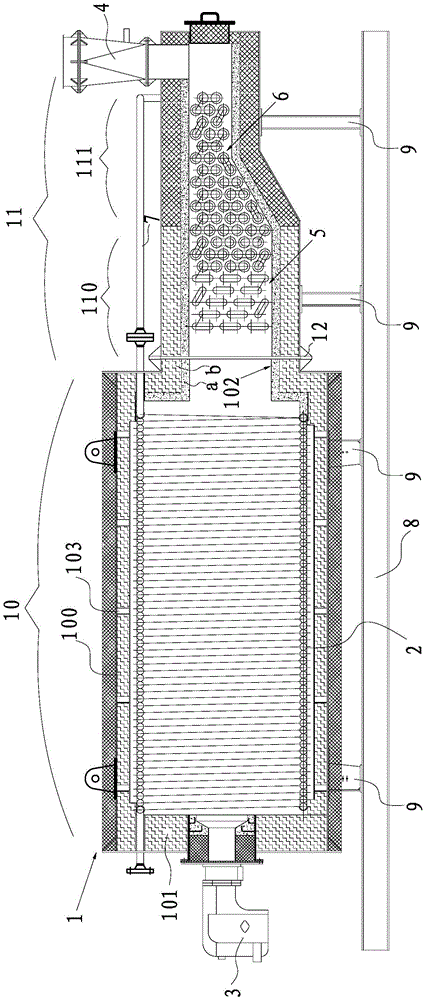
[0020] Such as figure 1 and figure 2 As shown, the skid-mounted water injection boiler provided in this example includes a furnace body 1 extending along the horizontal direction, a furnace tube 2 arranged inside the furnace body 1, and is arranged at one end of the furnace body 1 and communicates with the furnace body 1. The burner 3, the chimney 4 that is arranged on the other end of body of heater 1. Wherein the furnace body 1 includes a radiation heating section 10 and a convection heating section 11, the furnace tube 2 is a spiral coil and extends along the length direction of the furnace body 1 and is located in the radiation heating section 10, the chimney 4 is located at the tail of the convection heating section 11, and the water injection The boiler also includes a preheating tube 5 located in the convection heating section 11 for preheating the water or medium injected into the furnace tube to raise the temperature, and is arranged on the right side of the pre...


PUM


Abstract

The invention discloses a skid-mounted water injection boiler, which includes a furnace body, a furnace tube, a burner, and a chimney, wherein the furnace body includes a radiation heating section and a convection heating section, and the furnace tube is a spiral coil tube along the length of the furnace body. The direction extension is located in the radiation heating section, the chimney is located at the tail of the convection heating section, and the water injection boiler also includes a preheating tube located in the convection heating section for preheating the water or medium injected into the furnace tube, and along the convection heating section. The extension direction is arranged on the right side of the preheating pipe and connected with the heating pipe, the connecting pipe for connecting the heating pipe with the furnace pipe, the skid seat arranged under the furnace body along the extending direction of the furnace body, And connecting seats respectively used for connecting the radiation heating section and the convection heating section to the skid base. The invention not only enables the furnace tube to be heated evenly in the radiant section, but also effectively reduces the low-temperature corrosion at the tail end of the furnace body. At the same time, the furnace body and the burner are integrated into a skid, which is convenient for transportation and on-site installation.

Description

technical field [0001] The invention relates to a skid-mounted water injection boiler, in particular to a skid-mounted gas (oil) water injection boiler used for thermal recovery of crude oil in an oil field. Background technique [0002] Oilfield crude oil thermal recovery refers to the heating of viscous crude oil that is difficult to extract underground. However, after the oilfield is put into development, as the production time increases, the energy of the oil layer itself will be continuously consumed, resulting in a continuous decline in the pressure of the oil layer. A large amount of crude oil is degassed, its viscosity increases, the production of oil wells is greatly reduced, and even the injection and production will be stopped, resulting in a large amount of dead oil left underground that cannot be recovered. [0003] In order to solve the above technical problems, by injecting high-pressure hot water or steam with a certain temperature into the oil layer, it...

Claims


Application Information

Patent Timeline
Patent Type & Authority Patents(China)
IPC IPC(8): F24H1/40F24H1/08F24H9/18F24H9/00
Inventor 范文斌魏练
Owner JIANGNAN BOILERS & PRESSURE VESSELS ZHANGJIAGANG
Why Eureka
Try Eureka