an automatic extractor

An automatic and transmission belt technology, which is applied in the manufacture of inductors/transformers/magnets, coils, electrical components, etc., can solve the problems of high labor intensity, avoid damage to the guide pins, reduce impact, and improve efficiency.

Inactive Publication Date: 2016-03-02
ZHONGJIANG KAIXUN ELECTRONICS
View PDF3 Cites 0 Cited by
  • Summary
  • Abstract
  • Description
  • Claims
  • Application Information

AI Technical Summary

Problems solved by technology

[0004] The invention provides an automatic extractor, which solves the problem of high manual labor intensity and achieves the purpose of improving the efficiency of straightening the needle

Method used


Image

  • an automatic extractor
  • an automatic extractor

Examples


Embodiment 1

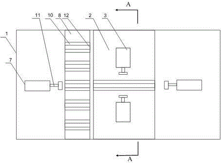
[0021] like figure 1 As shown, the present embodiment includes a working frame 1, and the working frame 1 is provided with a needle pulling device 2 and two driving mechanisms. The needle pulling device 2 is arranged between the two driving mechanisms, and also includes a transmission mechanism. Between the mechanism and the needle pulling device 2, a displacement sensor is also installed on the transmission mechanism; wherein the needle pulling device 2 includes a top plate 6, an upper top cylinder 5 and a baffle plate 4, the baffle plate 4 is arranged under the top plate 6, and the baffle plate 4 is fixed on On the working frame 1, the top plate 6 is connected to the top of the baffle plate 4, the upper top cylinder 5 is arranged vertically, and the telescopic end of the upper top cylinder 5 passes through the baffle plate 4 and is connected with the bottom surface of the top plate 6, and there are also two sets on the working frame 1. The clamping cylinder 3, the baffle is ...

Embodiment 2

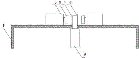
[0024] like figure 1 and figure 2 As shown, rubber pads are also provided on the end faces of the two ends of the baffle 4 in this embodiment, and the splints 9 at the left and right ends are driven by the power equipment to quickly move toward the baffle 4, and the guide pins are placed between the baffle 4 and the splint 9. , the fast-moving splint 9 is directly in contact with the guide pin and the baffle plate 4, which will easily cause a certain impact on the guide pin, causing deformation of the guide pin and affecting its performance; The splint 9 provides a certain amount of cushioning to reduce the impact of the splint 9 on the guide needle, so as to ensure that the guide needle is clamped and fixed while preventing the guide needle from being damaged or deformed.


PUM


Abstract

The invention discloses an automatic pulling and poking device which comprises a work frame. A pin poking device and two driving mechanisms are arranged on the work frame, and the pin poking device is arranged between the two driving mechanisms. The automatic pulling and poking device further comprises a conveying mechanism arranged among the driving mechanisms and the pin poking device, and a displacement sensor is further arranged on the conveying mechanism. The displacement sensor can accurately control movement of the conveying mechanism, namely one driving mechanism can well push a box body to the pin poking device. When the pulling and poking procedure is completed, the other driving mechanism pushes the box body to the conveying mechanism, and finally the conveying mechanism is controlled to convey the pulled and poked box body to the collecting position. Automation of correcting a guide pin of a network transformer is achieved, and correction efficiency is improved.

Description

technical field [0001] The invention relates to a network transformer, in particular to an automatic extractor. Background technique [0002] The network transformer is generally installed near the input end of the network card. When working, the uplink data signal sent by the transceiver enters from Pin16-Pin15 of the network transformer, outputs from Pin10-Pin11, passes through the RJ45 type adapter, and then passes through the unshielded twisted pair The downlink data signal sent by the server passes through another pair of unshielded twisted pair and RJ45 type adapter, enters through Pin7-Pin6, outputs through Pin1-Pin2, and then sends it to the transceiver of the network card. The role of the network transformer is: first, it can enhance the signal and make its transmission distance longer; second, it can isolate the chip end from the outside, greatly enhance the anti-interference ability, and add a great protection to the chip (such as anti-lightning strike) ; Third, ...

Claims


Application Information

Patent Timeline
Patent Type & Authority Patents(China)
IPC IPC(8): H01F41/00H01F41/04
Inventor 黄建国黄建云黄旭
Owner ZHONGJIANG KAIXUN ELECTRONICS
Why Eureka
Try Eureka