
Rotation heat storage type waste gas incinerating device

An incineration device and regenerative technology, which is applied to incinerators, combustion methods, combustion types, etc., can solve the problems of difficult installation and replacement of regenerators, waste of regenerator materials, and difficulty in processing regenerators. Cross-contamination occurs, maintenance is easy, and the effect of improving the average thermal decomposition rate

Inactive Publication Date: 2014-01-01
ZHEJIANG HUANTAI ENVIRONMENTAL PROTECTION EQUIP
View PDF10 Cites 20 Cited by
  • Summary
  • Abstract
  • Description
  • Claims
  • Application Information

AI Technical Summary

Problems solved by technology

However, this kind of cylindrical incinerator divides the regenerator into sectors, so it is difficult to install and replace the regenerator, and the granular regenerator has a large resistance to the gas, and the fan consumes a lot of energy. If the honeycomb heat storage body is filled, it is necessary to make the heat storage body into a fan shape with the same diameter or cut it into a fan shape, which will inevitably cause difficulties in processing the heat storage body or cause waste of heat storage body materials.

Method used


Image

  • Rotation heat storage type waste gas incinerating device
  • Rotation heat storage type waste gas incinerating device
  • Rotation heat storage type waste gas incinerating device

Examples


Embodiment Construction

[0023] The following are specific embodiments of the present invention and in conjunction with the accompanying drawings, the technical solutions of the present invention are further described, but the present invention is not limited to these embodiments.

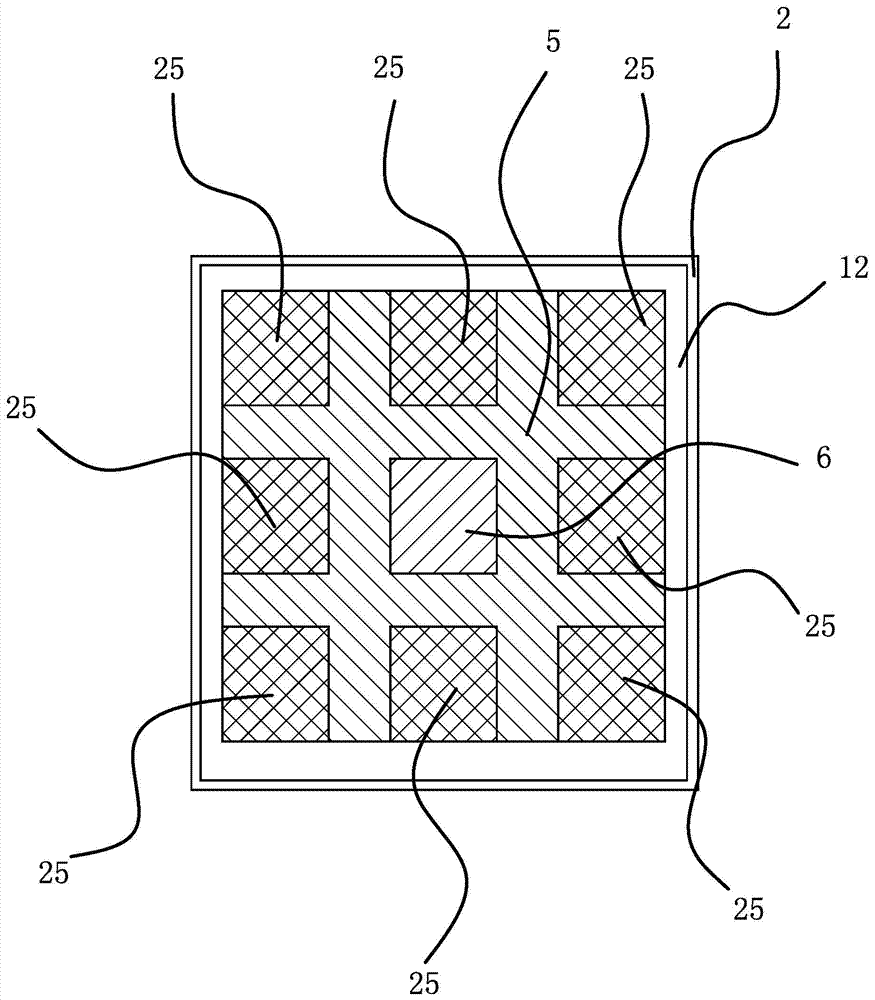
[0024] figure 1 , figure 2As shown, the rotary regenerative waste gas incinerator includes a rotary reversing valve 1 and an incinerator 2 with a square cavity. The rotary reversing valve 1 has an intake area 17, an exhaust area 20, a purge area 23 and a blind area 24. . The upper part of the cavity of the incinerator 2 is a combustion chamber 3, the upper part of the combustion chamber 3 is provided with a burner 4, and the lower part of the cavity is provided with a partition 5 that divides the cavity into nine square chambers 6 in the form of three columns and three columns. . The square chamber 6 located in the center is sealed, and the remaining eight square chambers 6 are provided with a regenerator 7 and a grid ...


PUM


Abstract

The invention provides a rotation heat storage type waste gas incinerating device and belongs to the technical field of environmental protection devices. The rotation heat storage type waste gas burning device solves the problems that a cylindrical incinerator body of an existing waste gas incinerator divides a heat storage chamber into sector-shaped parts, and installing and replacing a heat storage body are difficult. The rotation heat storage type waste gas burning device comprises a rotation reversing valve and an incinerator with a square cavity. The upper portion of the cavity of the incinerator is a combustion chamber, and the lower portion of the cavity is provided with partition boards dividing the lower portion of the cavity into nine square cavity bodies which are arranged in three rows and three columns. The center square cavity body is sealed, the rest eight peripheral square cavity bodies are internally provided with heat storage bodies, and the bottoms of the rest eight peripheral square cavity bodies are provided with grids capable of supporting the heat storage bodies, and therefore heat storage chambers are formed. All the heat storage chambers are communicated with an air inlet zone, an air discharge zone, a blowing and sweeping zone and a blind zone of the rotation reversing valve through connection air pipes respectively. Due to the fact that the cavity of the incinerator is arranged to be square, the cavity can be matched with the heat storage chambers more easily. The heat storage bodies are easy to manufacture and easy to maintain.

Description

technical field [0001] The invention belongs to the technical field of environmental protection equipment, and relates to a waste gas incineration treatment device, in particular to a rotary regenerative waste gas incineration device. It is used in the incineration treatment of organic waste gas, highly toxic gas and malodorous gas. It has the characteristics of high heat recovery efficiency, high purification efficiency and high equipment safety. Background technique [0002] Using incineration to treat organic waste gas, highly toxic gas and malodorous gas is a very effective treatment method. The principle is to use high heat to directly oxidize and decompose harmful substances in the waste gas components, such as oxidizing organic matter into CO 2 and H 2 0. In order to save incineration costs, regenerative incineration methods are mostly used, such as a kind of organic waste gas regenerative incinerator disclosed in Chinese patent CN01207962. hot process. However, w...

Claims


Application Information

Patent Timeline
IPC IPC(8): F23G7/06
Inventor 王奇志
Owner ZHEJIANG HUANTAI ENVIRONMENTAL PROTECTION EQUIP
Learn More