
Highway Tunnel Lighting Control System

A tunnel lighting control and lighting control technology, which is applied in lighting devices, outdoor lighting, fixed lighting devices, etc., can solve the problems of huge energy waste in lighting systems, achieve the effects of reducing operating costs, improving luminous efficiency, and reducing power consumption

Active Publication Date: 2016-05-25
GUANGXI TRANSPORTATION SCI & TECH GRP CO LTD
View PDF1 Cites 0 Cited by
  • Summary
  • Abstract
  • Description
  • Claims
  • Application Information

AI Technical Summary

Problems solved by technology

Even if this control method adopts a fully automatic five-level dimming system, its step-like brightness increases and decreases, but it still causes a huge waste of energy consumption in the lighting system

Method used


Image

  • Highway Tunnel Lighting Control System

Examples


Embodiment 1

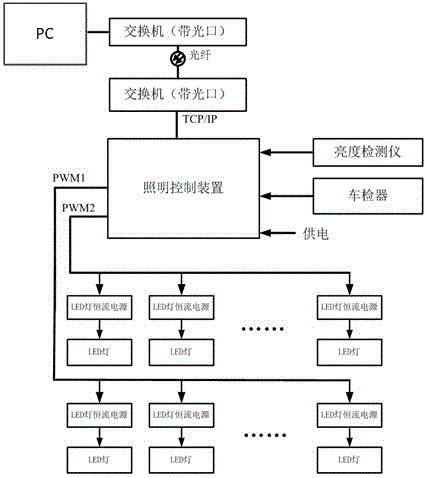
[0026] Embodiment 1: as figure 1 As shown, the monitoring computer uses a switch with an optical port to connect to the lighting controller installed on the intelligent dimming control system in the tunnel through the TCP / IP protocol. The lighting controller is a Beckhoff PLC. Luminance detector and vehicle detector measure signal processing, among which the vehicle detector adopts South African TD634ES 4-channel coil vehicle detector, and the model of brightness detector is Lance LUM102-T. The vehicle detector realizes the optical fiber connection with the lighting controller through the optical transceiver, and the model of the optical transceiver is Nandrolone OTS010B-ST-SR. The brightness detector is connected with the lighting controller through the analog input signal line. The output signal PWM1 of the lighting controller is connected in parallel with the LED lamp constant current power supply in the enhanced lighting circuit of the tunnel entrance section through the ...

Embodiment 2

[0027] Embodiment 2: According to the connection method in Implementation 1, the lighting control device receives the measurement signals of the brightness detector and the vehicle detector, and the lighting control device is connected through the PWM bus and outputs the PWM signal to the constant current power supply of the LED lamp in the lighting circuit in the tunnel. The lamp constant current power supply is connected to the LED lamp. When the PWM signal is at a high level, the current output of the LED lamp constant current power supply is at a minimum value, and when the said PWM signal is at a low level, the current output of the LED lamp constant current power supply is at a maximum value. The lighting control device outputs at least two PWM signals, including PWM1 and PWM2; the PWM1 output is set by the lighting control device according to the signal processing results of the brightness detector and the vehicle detector, and the PWM2 output is set by the lighting cont...

Embodiment 3

[0028]Embodiment 3: On the basis of Embodiment 1 and Embodiment 2 above, a maintenance coefficient module is set in the lighting control device, and the maintenance coefficient module adjusts the PWM signal output according to the maintenance coefficient of the LED lamps in the tunnel.


PUM


Abstract

The invention discloses anillumination control system of tunnel lamps on expressways. The illumination control system comprises an illumination control device, wherein the illumination control device is connected with an upper computer by an exchanger, receives signals measured by a brightness detecting instrument and a vehicle detector by a bus, and is connected with and outputs PWM (Pulse Width Modulation) signals to a constant-current power supply of an LED (Light Emitting Diode) lamp in an illumination loop in a tunnel by a PWM bus; the constant-current power supply of the LED lamp is connected with the LED lamp; when the PWM signals are in high level, the current output of the constant-current power supply of the LED lamp is the minimum value, and when the PWM signals are in low level, the current output of the constant-current power supply of the LED lamp is a maximum value; and the illumination control device outputs at least two paths of PWM signals, and the number of the paths is set by the illumination control device according to processed results of the signals measured by the brightness detecting instrument and the vehicle detector. The illumination control system disclosed by the invention has the advantages that under the conditions with different light environments, vehicles or novehicles and different vehicle flows, automatic stepless regulation is realized for tunnel illumination on the expressways, so that the light-emitting efficiency of the lamps is improved and the consumption of the electric energy for tunnel illumination is reduced.

Description

technical field [0001] The invention relates to an LED lighting control system for highway tunnels, in particular to an LED lighting control system based on PWM control and applied to highway tunnels, belonging to the field of highway tunnel lighting. Background technique [0002] Lighting energy consumption is a key energy-consuming unit in my country, among which highway tunnel lighting, especially expressway tunnel lighting, is also known as a major lighting energy-consuming household. Due to the great difference between highway tunnel lighting and road lighting, especially the visual adaptation of car drivers when they exit and enter the tunnel, the dimming control of highway tunnel lighting has become a new research topic. Under various complex environments such as different seasons, different time periods, different weather, and different traffic volumes, tunnels of different sizes and lengths have different requirements for lighting brightness. However, the current t...

Claims


Application Information

Patent Timeline
Patent Type & Authority Patents(China)
IPC IPC(8): F21S8/00H05B37/02F21W131/101
CPCY02B20/40
Inventor 郑明德徐莉华徐韶华胡红波李祖文陈志
Owner GUANGXI TRANSPORTATION SCI & TECH GRP CO LTD
Learn More