
Circular polarization crossed dipole antenna and manufacturing method thereof

A technology of crossed dipoles and dipoles, which is applied in the field of circularly polarized crossed dipole antennas and its preparation, can solve the problems of low gain, complex techniques for widening the bandwidth of circularly polarized antennas, and increased costs, and reduce manufacturing costs , Small size, wide impedance bandwidth effect

Active Publication Date: 2013-12-25
SHENZHEN UNIV
View PDF5 Cites 18 Cited by
  • Summary
  • Abstract
  • Description
  • Claims
  • Application Information

AI Technical Summary

Problems solved by technology

[0004] In view of the above-mentioned deficiencies in the prior art, the object of the present invention is to provide a circularly polarized crossed dipole antenna and its preparation method, aiming to solve the problems of complex technologies for widening the bandwidth of circularly polarized antennas, increasing costs, and low gain.

Method used


Image

  • Circular polarization crossed dipole antenna and manufacturing method thereof
  • Circular polarization crossed dipole antenna and manufacturing method thereof
  • Circular polarization crossed dipole antenna and manufacturing method thereof

Examples


Embodiment Construction

[0029] The present invention provides a circularly polarized cross dipole antenna and a preparation method thereof. In order to make the objectives, technical solutions and effects of the present invention clearer and clearer, the present invention will be described in further detail below. It should be understood that the specific embodiments described herein are only used to explain the present invention, but not to limit the present invention.

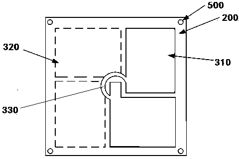
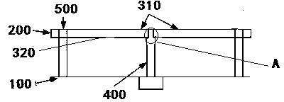
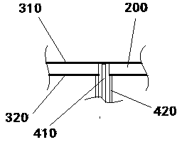
[0030] Such as figure 1 , figure 2 , image 3 A circularly polarized cross dipole antenna is shown, which is used in ISM frequency band wireless communication, wherein the antenna includes a metal reflector 100, a dielectric substrate 200 arranged above the metal reflector 100, and The cross dipole radiating unit on the upper and lower surfaces of the dielectric substrate 200, and the coaxial feed unit 400 connected to the cross dipole radiating unit, the cross dipole radiating unit includes printed on the dielectric substrate, respect...


PUM


Abstract

The invention discloses a circular polarization crossed dipole antenna and a manufacturing method of the circular polarization crossed dipole antenna. The circular polarization crossed dipole antenna comprises a metal reflection board, a medium substrate located above the metal reflection board, crossed dipole radiation units arranged on the upper surface and the lower surface of the medium substrate respectively, and a coaxial feed unit connected with the crossed dipole radiation units. The crossed dipole radiation units comprise an upper dipole and a lower dipole which are arranged on the upper surface and the lower surface of the medium substrate respectively. The coaxial feed unit comprises an inner conductor and an outer conductor. The inner conductor penetrates through the metal reflection board and the medium substrate to be connected with the upper dipole. The outer conductor penetrates through the metal reflection board to be connected with the lower dipole. The crossed dipole antenna is led to a micro-strip patch, so that the circular polarization crossed dipole antenna not only has the advantages that a micro-strip antenna is small in size, light in weight, conformal with an application platform easily and easy to integrate, but also has the advantages of the wide impedance bandwidth, the circular polarization bandwidth, high gains and low manufacturing cost.

Description

Technical field [0001] The invention relates to the technical field of microwave antennas, in particular to a circularly polarized cross dipole antenna and a preparation method thereof. Background technique [0002] The rapid development of wireless technology has led to the great development of antenna technology. In particular, circularly polarized antennas have been widely used in various fields of wireless communication, such as satellite communications, radio frequency devices (RFID), wireless local area networks (WLAN), The Global Positioning System (GPS) and the Beidou positioning system independently developed by my country all use circularly polarized antennas. The wider the application, the higher the requirements for antenna performance. In many applications, both the antenna impedance bandwidth and the circular polarization bandwidth (axial ratio bandwidth) are very wide. There are many ways to broaden the bandwidth of a circularly polarized antenna, such as attaching...

Claims


Application Information

Patent Timeline
IPC IPC(8): H01Q1/38H01Q1/50H01Q19/10
Inventor 何业军贺卫刘航杨洁孙桂圆
Owner SHENZHEN UNIV
Learn More