Eureka AIR delivers breakthrough ideas for toughest innovation challenges, trusted by R&D personnel around the world.

Cable type fault detector

A detector and cable-type technology, applied in the field of cable-type fault detectors, can solve the problems of low fault judgment accuracy, low reliability, and large load current measurement error, achieve high fault judgment accuracy, and improve current measurement. The effect of accuracy and fault measurement error is small

Inactive Publication Date: 2013-12-25
WILLFAR INFORMATION TECH CO LTD
View PDF8 Cites 7 Cited by
  • Summary
  • Abstract
  • Description
  • Claims
  • Application Information

AI Technical Summary

Problems solved by technology

[0004] 1. The fault indicator with a single current transformer structure, the induction power supply and the measurement circuit share a transformer, which has a great impact on the measurement accuracy, the fault judgment accuracy is not high, and the load current measurement error is large
[0005] 2. The zero-sequence current transformer is not connected to the short-circuit fault indicator, and the measurement uses a disposable lithium battery as the main power supply. The lithium battery has limited power and the service life of the equipment is short
[0006] 3. The fault indicator reports the fault information through the communication mode of plastic optical fiber. The field wiring of plastic optical fiber is difficult, the reliability is low, and it is difficult to popularize and apply it in batches.

Method used


Image

  • Cable type fault detector
  • Cable type fault detector
  • Cable type fault detector

Examples


Embodiment Construction

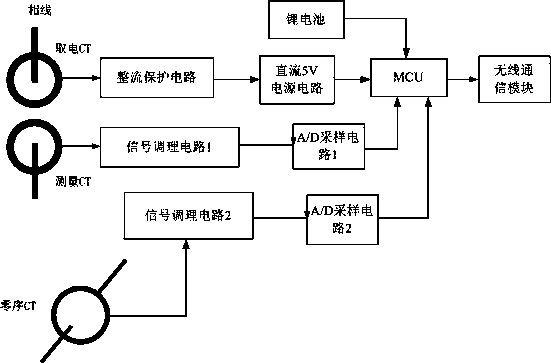
[0025] Medium-voltage power distribution lines generally adopt a three-phase three-wire structure. The present invention calculates short-circuit and grounding signals by adopting and analyzing A, B, and C three-phase currents and zero-sequence currents.

[0026] The invention includes a short-circuit fault indicator and a zero-sequence current transformer; the short-circuit fault indicator is installed on the A-phase, B-phase and C-phase lines of the distribution network. The zero-sequence current transformer is installed at the confluence of A-phase, B-phase and C-phase lines.

[0027] The short-circuit fault indicator integrates two current transformers inside, one current transformer (power-taking current transformer) provides the induction power supply for the present invention; the other current transformer (measurement current transformer) provides the phase current transmission signal for the present invention , used for short-circuit fault calculation and load current...


PUM


Abstract

The invention discloses a cable type fault detector. The cable type fault detector comprises a short-circuit fault indicator and a zero-sequence current mutual inductor. The short-circuit fault indicator comprises a power-taking current mutual inductor, a measuring current mutual inductor, a CT (Captive Test) power supply circuit, a phase current measuring circuit, a wireless communication module, an MCU (Microprogrammed Control Unit) and a zero-sequence current measuring circuit, wherein the power-taking current mutual inductor is connected with the power supply end of the MCU by virtue of the CT power supply circuit; the measuring current mutual inductor is connected with an I / O (Input / Output) port of the MCU by virtue of the phase current measuring circuit, and used for transmitting a detected phase current transmitting signal to the MCU; the zero-sequence current mutual inductor is connected with the A / D (Analog to Digital) sampling port of the MCU by virtue of the zero-sequence current measuring circuit, and used for transmitting a detected current transmitting signal to the MCU; the serial interface of the wireless communication module is connected with the I / O port of the MCU by virtue of an SPI (Single Program Initiation) bus. The cable type fault detector disclosed by the invention adopts a structural form with a plurality of current mutual inductors to carry out short-circuit and grounding fault detection, thereby effectively improving the current measuring precision and lowering the equipment start-up current.

Description

technical field [0001] The invention relates to a fault detector, in particular to a cable type fault detector. Background technique [0002] In distribution automation system, fault location detection is a very important function. With the development of society and economy, the load and power supply radius of cable-type distribution lines continue to increase, the number of branch lines continues to increase, and the structure of the lines becomes more and more complex, resulting in an increase in the failure rate of the lines, making it difficult to check and troubleshoot faults. How to minimize the line failure rate and minimize the troubleshooting time is one of the important contents of high-quality electric power service. [0003] At present, the traditional cable-type distribution line fault detection, the short-circuit fault indicator generally adopts a single transformer structure, the zero-sequence current transformer is not connected to the short-circuit fault i...

Claims


Application Information

Patent Timeline
Patent Type & Authority Applications(China)
IPC IPC(8): G01R31/02G01R31/08
Inventor 李君黄雄凯阳武许健刘刚周到
Owner WILLFAR INFORMATION TECH CO LTD
Why Eureka
Eureka Blog
Learn More