Magnetic circuit mounting structure for detachable open-loop-type Hall current sensor

A technology of Hall current and installation structure, applied in the direction of measuring current/voltage, measuring current only, voltage/current isolation, etc., can solve the problems of increasing labor cost, not increasing much, processing grounding wire, and time-consuming welding, etc. Current measurement accuracy, stable temperature characteristics, and the effect of expanding application fields

Pending Publication Date: 2019-08-09
南京普肯传感科技有限公司
View PDF0 Cites 0 Cited by
  • Summary
  • Abstract
  • Description
  • Claims
  • Application Information

AI Technical Summary

Problems solved by technology

[0005] 1. The open-loop Hall current sensor generally uses a silicon steel sheet to wind and process the magnetic core, and the surface of the silicon steel sheet has an oxide layer, which cannot be welded directly. The oxide layer on the surface of the silicon steel sheet must be ground with a grinding wheel before welding, and the magnetic The surface area of ​​the core is large and the heat capacity is large. It must be soldered with a high-power electric soldering iron. Therefore, the processing and welding of the ground wire is very time-consuming, which increases labor costs and seriously affects the production efficiency of the Hall current sensor. It cannot be automated in large quantities. Production
[0006] 2. Copper tape is used to wrap around the outside of the magnetic core. When shielding the air gap of the magnetic core, it is not easy to fix the copper tape on the outside of the magnetic core; The production efficiency is reduced, more materials are used for winding copper tape, and the cost is also increased during mass production. This is laborious and does not improve the anti-interference ability of the open-loop Hall current sensor much.
[0007] 3. When the PCB board is installed in the shell, in order to avoid short circuit between the pins of the Hall element and the air gap of the magnetic core, each Hall element must be manually wrapped with insulating tape, which cannot realize automatic production
[0008] 4. The detachable open-loop Hall current sensor is very difficult to install and fix the magnetic core. It is necessary to position the magnetic core in the plastic shell and fix it with potting glue. However, it takes time for the potting glue to cure and cannot ensure the air gap. Width consistency will affect the production efficiency and parameter consistency of sensors in mass production
[0009] The shape of the detachable open-loop Hall current sensor is generally circular or square. As the temperature changes, the thermal expansion coefficients of the plastic material, potting compound and soft magnetic material used in the housing cannot be consistent, resulting in a non-constant thermal expansion coefficient of the air gap width, which makes the output amplitude of the detachable open-loop Hall current sensor As the temperature changes nonlinearly, linear compensation cannot be performed, resulting in poor temperature stability of the open-loop Hall current sensor, which seriously affects the measurement accuracy of the open-loop Hall current sensor

Method used


Image

  • Magnetic circuit mounting structure for detachable open-loop-type Hall current sensor
  • Magnetic circuit mounting structure for detachable open-loop-type Hall current sensor
  • Magnetic circuit mounting structure for detachable open-loop-type Hall current sensor

Examples


Embodiment Construction

[0030] In order to make the technical solutions of the present invention clearer and clearer for those skilled in the art, the present invention will be further described in detail below in conjunction with the embodiments and the accompanying drawings, but the embodiments of the present invention are not limited thereto.

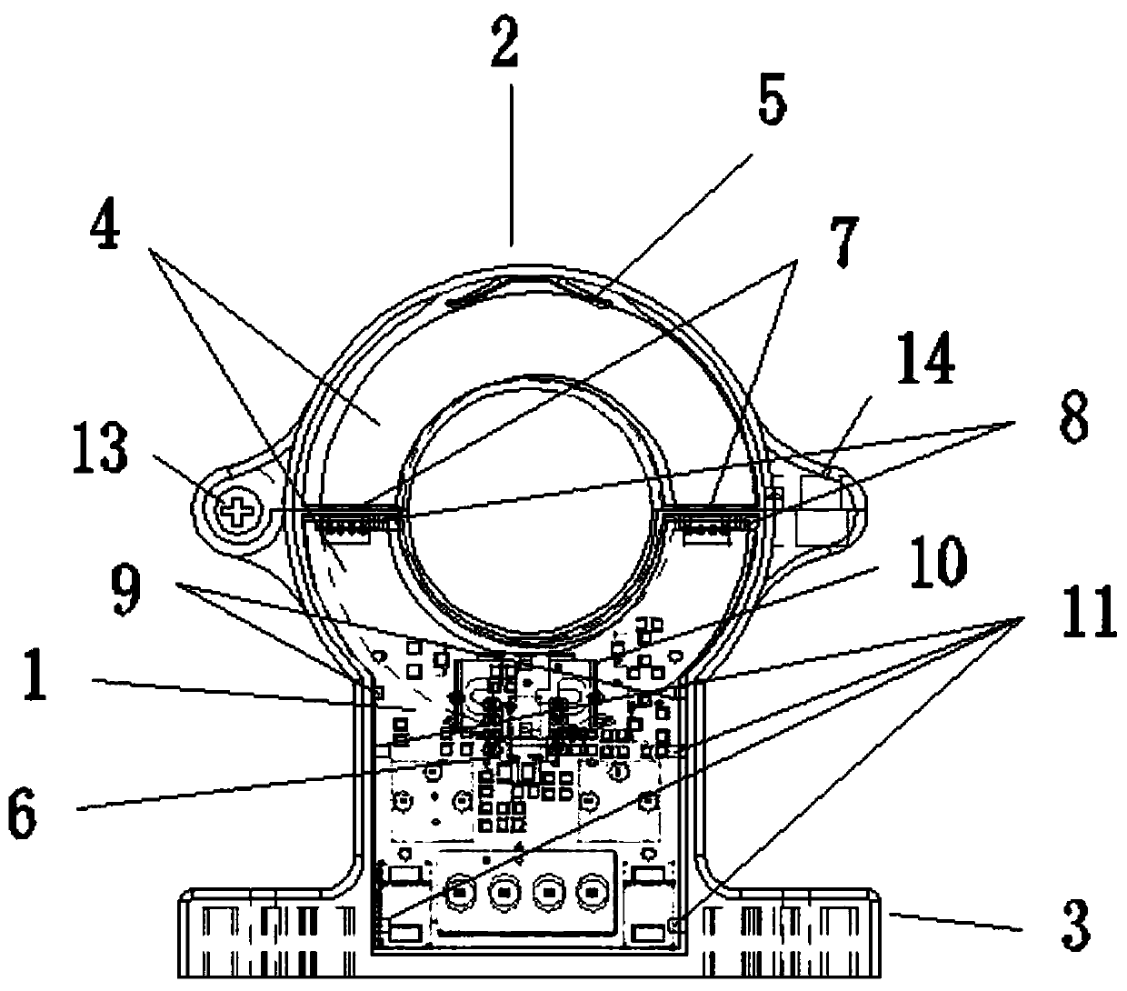
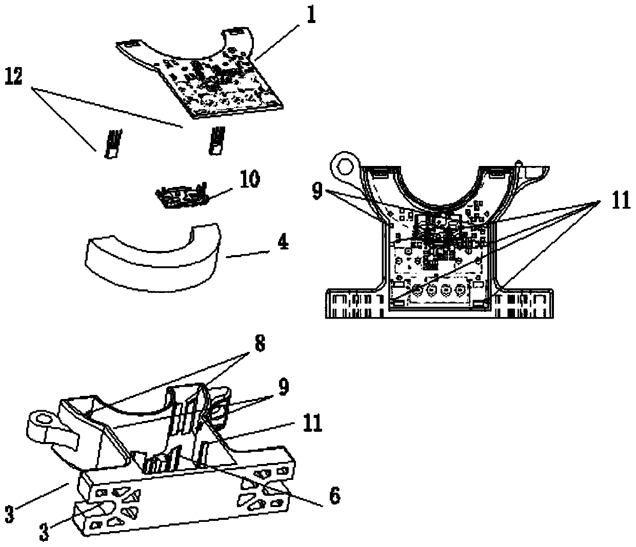
[0031] Such as Figure 1-Figure 4 As shown, the magnetic circuit mounting structure for a detachable open-loop Hall current sensor provided by this embodiment includes a housing and a magnetic core 4 with two symmetrically distributed air gaps of the same width and installed in the housing. The PCB board 1 and the shielding frame 10 installed on the PCB board 1, the shape of the core hole and the magnetic core on the shell are circular, the size of the core hole is 21mm in diameter, and the shell is divided into upper and lower parts based on the center line of the core hole. Remove the two parts: the upper shell body 2 and the lower shell body 3. The upper sh...


PUM


Abstract

The invention discloses a magnetic circuit mounting structure for a detachable open-loop-type Hall current sensor, and belongs to the technical field of magnetic circuit mounting. The magnetic circuitmounting structure comprises a shell, and further comprises a PCB, a magnetic core and a shielding frame which are mounted in the shell; an upper body of the shell is provided with a magnetic core mounting area, a baffle and an upper body elastic buckle structure; a lower body of the shell is provided with a magnetic core mounting area, two Hall element mounting areas and a PCB mounting area, wherein the magnetic core mounting area is provided with a lower body elastic buckle structure; the Hall element mounting areas are provided with PCB mounting table columns, Hall element inserting grooves and magnetic core baffles; the PCB mounting area is provided with mounting columns and buckles; and the shielding frame is provided with elastic sheets and grounding pins, and the grounding pins penetrate through grounding welding holes in the PCB to be welded and grounded. According to the magnetic circuit mounting structure, during mounting, the magnetic core is flatly pushed to the bottom through the magnetic core baffles and the elastic buckle structures, a ground wire is not welded to the magnetic core, the magnetic core is good in air gap width consistency and temperature stability, Hall elements do not need to be wrapped with insulation belts, and the PCB is mounted and not skewed.

Description

Technical field [0001] The invention relates to a magnetic circuit circuit mounting structure, in particular to a magnetic circuit circuit mounting structure for a detachable open-loop Hall current sensor, and belongs to the technical field of magnetic circuit circuit mounting. Background technique [0002] The open-loop Hall current sensor is composed of a Hall element, a magnetic core with an air gap made of soft magnetic material, and an appropriate amplifier circuit. The working process is: the Hall element is used to detect the magnetic induction intensity generated by the primary current in the core air gap, and the output voltage of the Hall element is adjusted and amplified to 0-4V or 0-5V by an amplifier. Since the working process of this current sensor is an open loop structure, it is called an open-loop Hall current sensor. [0003] Since the through-core open-loop Hall current sensor generally adopts an integral through-core hole, which is used for the measurement of l...

Claims


Application Information

Patent Timeline
Patent Type & Authority Applications(China)
IPC IPC(8): G01R19/00G01R15/20
CPCG01R15/202G01R19/0092
Inventor 邹高芝魏义松苏本社
Owner 南京普肯传感科技有限公司
Why Eureka
Try Eureka