cutting device

A technology of cutting device and cutting unit, which is applied in the direction of metal processing, etc., can solve the problems of complex disassembly and installation of cutters, difficulty in precise control of cutting depth, and difficult adjustment of parallelism, so as to improve equipment production utilization and avoid cutting depth Not enough, save the effect of correction time

Active Publication Date: 2016-06-08
TCL CHINA STAR OPTOELECTRONICS TECH CO LTD
View PDF4 Cites 1 Cited by
  • Summary
  • Abstract
  • Description
  • Claims
  • Application Information

AI Technical Summary

Problems solved by technology

In order to completely cut the conductive film body 11 without cutting the release film 12, it is necessary to control the cutting depth of the cutting knife 211. However, since the conductive film body 11 has only tens of microns, the cutting depth is difficult to be accurately determined. control, it is easy to appear that the conductive film body 11 is not cut or the release film 12 is completely cut
At the same time, since the cutter 211 and the knife rest 212 are fixedly connected by two connecting parts 2111, the parallelism between the cutter 211 and the carrying platform 22 is difficult to adjust
In the actual cutting process, the phenomenon of cutting failure caused by the poor parallelism between the cutting knife 211 and the upper surface of the carrying platform 22 frequently occurs, such as Figure 2c As shown, the first end 211A of the cutter 211 has cut the release film 12 and the second end 211B has not completely cut off the conductive film body 11
[0009] To sum up, when the existing cutting device 20 cuts the opposite sex conductive film 10, it is prone to cutting failure, which reduces the yield of the product; at the same time, it takes a lot of time to correct the parallelism of the cutter before cutting. It takes a long time, and the disassembly and installation of the cutter is also relatively complicated, which seriously affects the production efficiency of the equipment

Method used


Image

  • cutting device
  • cutting device
  • cutting device

Examples


Embodiment 1

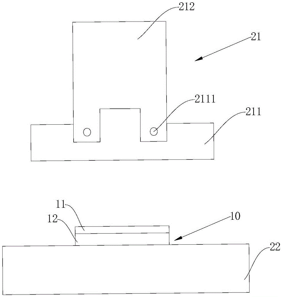
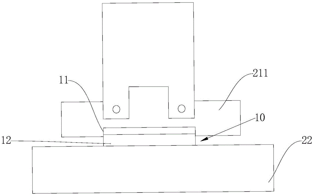
[0033] refer to Figures 3a-3e ,Such as Figure 3aAs shown, the cutting device provided in this embodiment includes a carrying platform 22 and a cutting unit 21 located above the carrying platform 22 , wherein the cutting unit 21 includes a cutting knife 211 and a knife holder 212 . The cutting device also includes a first stopper 231 and a second stopper 232 fixedly connected to the carrying platform 22 ; wherein, the upper ends of the first stopper 231 and the second stopper 232 are flush and parallel to the carrying platform 22 . When the cutter 211 is perpendicular to the carrying platform 22, the first stop 231 and the second stop 232 are used to keep a certain distance between the cutting edge of the cutting knife 211 and the carrying platform 22, so that the cutting depth of the cutting knife 211 can be precisely controlled. The middle part of the cutting knife 211 of the cutting device in this embodiment is provided with a connecting portion 2111, and the cutting knif...

Embodiment 2

[0037] refer to Figures 4a-4c , the cutting device provided in this embodiment is as Figure 4a As shown, the same as in Embodiment 1, the cutting device includes a carrying platform 22 and a cutting unit 21 positioned above the carrying platform 22, wherein the cutting unit 21 includes a cutting knife 211 and a knife holder 212. Unlike Embodiment 1, in In this embodiment, the stopper is fixedly connected with the cutter 211 instead of being connected with the carrying platform 22 . Wherein, the stopper includes a third stopper 233 and a fourth stopper 234 , the bottom ends of the third stopper 233 and the fourth stopper 234 are flush and parallel to the cutting edge of the cutting knife 211 . The middle part of the cutting knife 211 of the cutting device in this embodiment is provided with a connecting portion 2111, and the cutting knife 211 is hinged with the knife rest 212 through the connecting portion 2111, so that the cutting knife 211 can freely swing around the conne...


PUM


Abstract

The cutting device provided by the present invention includes a carrying platform and a cutting unit located above the carrying platform, the cutting unit includes a cutting knife and a knife holder, wherein a connecting portion is provided in the middle of the cutting knife, and the cutting knife passes through the The connecting part is hinged with the knife holder; the cutting device also includes a stopper between the cutter and the carrying platform, and after the cutting knife vertically cuts to the carrying platform, the stopper is used for Keep the blade of the cutting knife parallel to the carrying platform with a gap. The cutting device provided by the invention can be used for cutting the anisotropic conductive film, and can effectively avoid cutting failure of the anisotropic conductive film caused by insufficient cutting depth precision or poor parallelism of the cutter, thereby improving product yield.

Description

technical field [0001] The invention relates to the field of flat panel display (FlatPanelDisplay, FPD) production, in particular to a cutting device for anisotropic conductive film (Anisotropic ConductiveFilm, ACF). Background technique [0002] Flat panel displays are widely used due to their thin body and low power consumption. Existing flat panel displays generally include liquid crystal displays (LCDs) and organic light emitting diode displays (OLEDs). [0003] A liquid crystal display, or LCD (Liquid Crystal Display), consists of a certain number of color or black and white pixels, placed in front of a light source or reflective surface. Liquid crystal displays have low power consumption, high image quality, small size, and light weight, so they are favored by everyone and become the mainstream of displays. [0004] OLED displays, unlike LCDs, do not require a backlight and are made from very thin layers of organic paint and glass substrates that emit light when an el...

Claims


Application Information

Patent Timeline
Patent Type & Authority Patents(China)
IPC IPC(8): B26D3/08B26D7/26
CPCB26D7/26B26D1/045B26D3/08B26D7/2614B26D7/2628
Inventor 赵国栋宋涛刘明马涛
Owner TCL CHINA STAR OPTOELECTRONICS TECH CO LTD
Why Eureka
Try Eureka