
Flat type speaker having vibration-lead plate of PCB voice coil plates

A flat-panel speaker and guide plate technology, which is applied in the fixing/tightening of electrostatic transducer speakers, sensors, and diaphragms, can solve the problems of small bonding area, limitation of speaker vibration energy conduction, disconnection, etc., to shorten the project. , Solve the effect of product quality decline

Inactive Publication Date: 2013-12-11
DAHONG TECH CO LTD
View PDF3 Cites 8 Cited by
  • Summary
  • Abstract
  • Description
  • Claims
  • Application Information

AI Technical Summary

Problems solved by technology

[0007] However, the traditional voice coil plate is only pasted to the vibration plate when it is in an inclined state. Due to the small bonding area with the vibration plate, the traditional speaker has the problem of limited vibration energy transmission.
[0008] Moreover, the guide wires formed on the voice coil board are combined on the bottom frame, the voice coil board moves up or down, and the bottom frame is fixed, and the traditional speaker is prone to lead wire drop or disconnection.
[0009] In addition, in engineering, metal wires are usually used when the lead wires of the voice coil board are connected to the terminals of the chassis. Although they are connected by welding, this method has the problem of reducing the quality of the speaker.

Method used


Image

  • Flat type speaker having vibration-lead plate of PCB voice coil plates
  • Flat type speaker having vibration-lead plate of PCB voice coil plates
  • Flat type speaker having vibration-lead plate of PCB voice coil plates

Examples


Embodiment Construction

[0037] Next, with reference to the accompanying drawings, the structure and effects of the flat panel speaker with the vibration-guiding metal plate of the PCB voice coil board of the present invention will be described in detail.

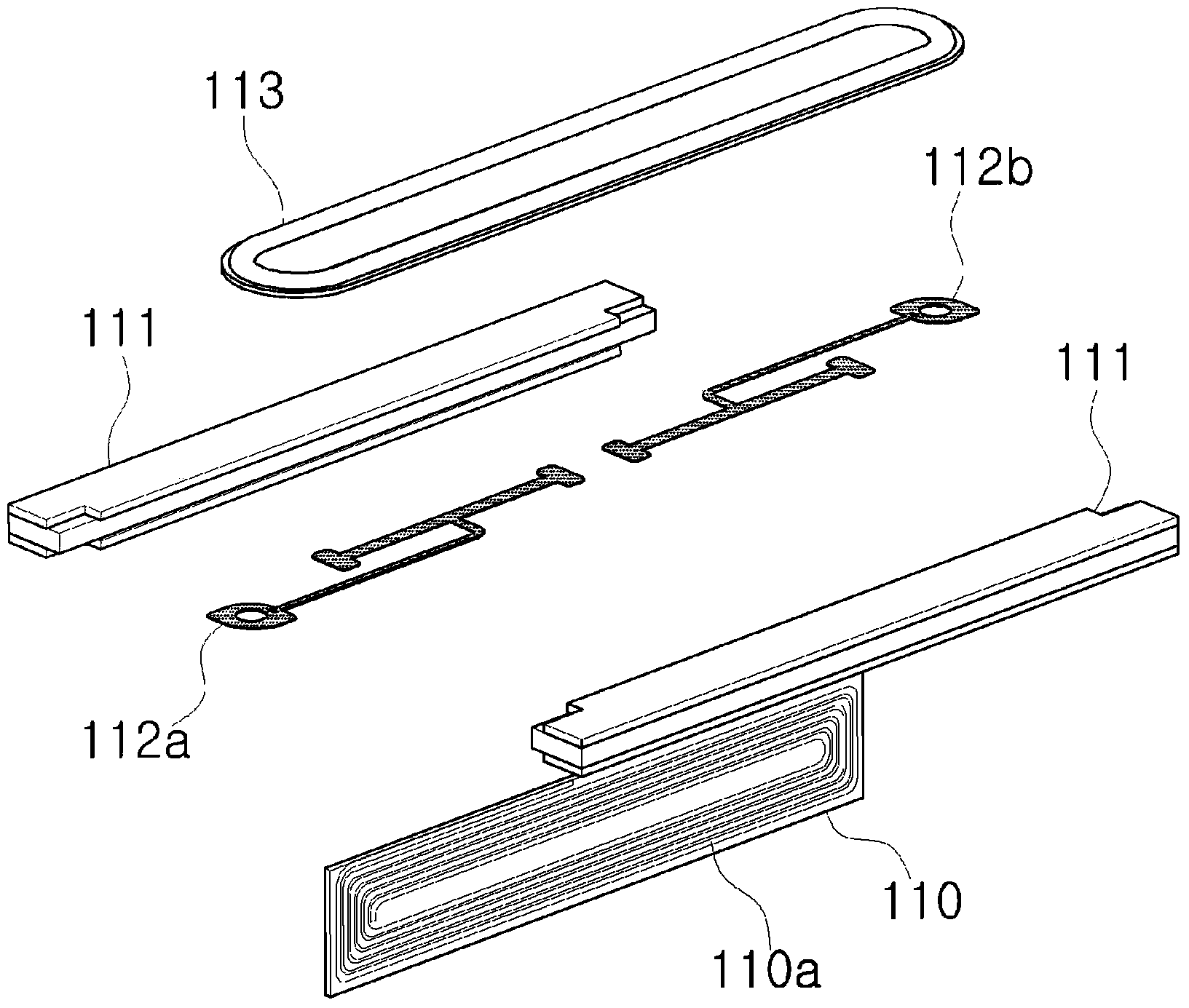
[0038] figure 1 It is an oblique view of the panel speaker with the vibration guide plate of the PCB voice coil board according to the present invention. figure 2 It is an exploded oblique view of a panel speaker having a vibration-guiding metal plate of a PCB voice coil plate according to the present invention.

[0039] Such as figure 1 Shown, the present invention has the panel loudspeaker of the vibration guide disk of PCB voice coil plate to be made of following several parts: voice coil plate (110), it is printed with the PCB (PRINT CIRCUIT BOARD: printed circuit board) form of tracking form pattern The voice coil (110a) is pattern printed; a pair of magnetic bodies (111) are at a certain interval on the left and right sides of the voice co...


PUM


Abstract

The invention relates to a flat type speaker, and more particularly relates to a flat type speaker having a vibration-lead plate of PCB voice coil plates, wherein the flat type speaker having the vibration-lead plate of the PCB voice coil plates is installed above the voice coil plates, and is capable of shortening production processes and solving the quality deterioration problem due to disconnection of a lead wire by increasing the vibration efficiency and eliminating the lead wire connected to the voice coil. The flat type speaker is characterized by comprising a pair of magnetic bodies formed in parallel at a predetermined interval with a magnet and a yoke; the voice coil plate inserted in the space between the magnetic bodies to form a voice coil with a spiral pattern printed thereon; and the vibration-lead plates having a first vibration-lead plate and a second vibration-lead plate which are physically separated, each having +, - terminals formed on the front ends thereof. The first vibration-lead plate and the second vibration-lead plate are each provided with a coil plate sheet, at least one wing sheet and a vibration plate, wherein the coil plate sheet is adhered to the upper end of the voice coil plate, one end of the at least one wing sheet is connected to the coil plate sheet and the other end is connected to the + or - terminals, and the vibration plate is disposed the upper ends of the vibration-lead plates and vibrates from the vibration received from the voice coil plates.

Description

technical field [0001] The invention relates to a flat-panel loudspeaker, in particular to a flat-panel loudspeaker installed on the upper part of the voice coil plate. By improving the vibration efficiency, the guide wire connected to the voice coil is not used, the production engineering can be shortened, and the problems caused by the disconnection of the guide wire can be improved. A flat-panel speaker with a vibration guide plate of a voice coil plate that has a problem of speaker quality degradation. Background technique [0002] A speaker has a voice coil and a diaphragm, which are located between magnets. When the voice coil moves, the diaphragm vibrates to produce sound. [0003] Flat-panel speakers are equipped with flat-plate voice coils and magnets. The magnets are arranged on both sides of the voice coil at a certain interval. According to Fleming's left-hand rule and Lawrence's principle, an organic electromotive force is generated, and a cycle is formed accord...

Claims


Application Information

Patent Timeline
Patent Type & Authority Applications(China)
IPC IPC(8): H04R9/04
CPCH04R1/06H04R7/24H04R9/047H04R9/04H04R19/02
Inventor 金东万权英地
Owner DAHONG TECH CO LTD
Learn More