
Hub blade automatic riveting machine and riveting method thereof

An automatic riveting and riveting machine technology, applied in the field of bicycle accessories, can solve problems such as unstable quality, numerous projects, and inability to automatically position

Inactive Publication Date: 2011-03-30
久钰车料(昆山)有限公司
View PDF0 Cites 0 Cited by
  • Summary
  • Abstract
  • Description
  • Claims
  • Application Information

AI Technical Summary

Problems solved by technology

[0002] As we all know, the status of bicycles has gradually improved recently, and has progressed from the earliest means of transportation to leisure and sports tools. Its requirements for quality are very high, and the riveting of the existing bicycle hub blades is due to the number of holes in the blades and the staggered holes on both sides of the blades. , the blade must be placed in the positioning mold by hand, which is a manual operation method, which is to place the blade in the B and C grooves of the existing riveting machine, and place the middle tube on the middle tube pressing lower die, The left and right hands press the switch at the same time, and the middle tube and the blade start to be riveted. This mode of operation requires a lot of work, and is limited by the number of holes in the blade, so it cannot be positioned automatically. It must be operated manually, which is costly and prone to work-related injuries, and the quality is not good. Stablize

Method used


Image

  • Hub blade automatic riveting machine and riveting method thereof
  • Hub blade automatic riveting machine and riveting method thereof
  • Hub blade automatic riveting machine and riveting method thereof

Examples


Embodiment Construction

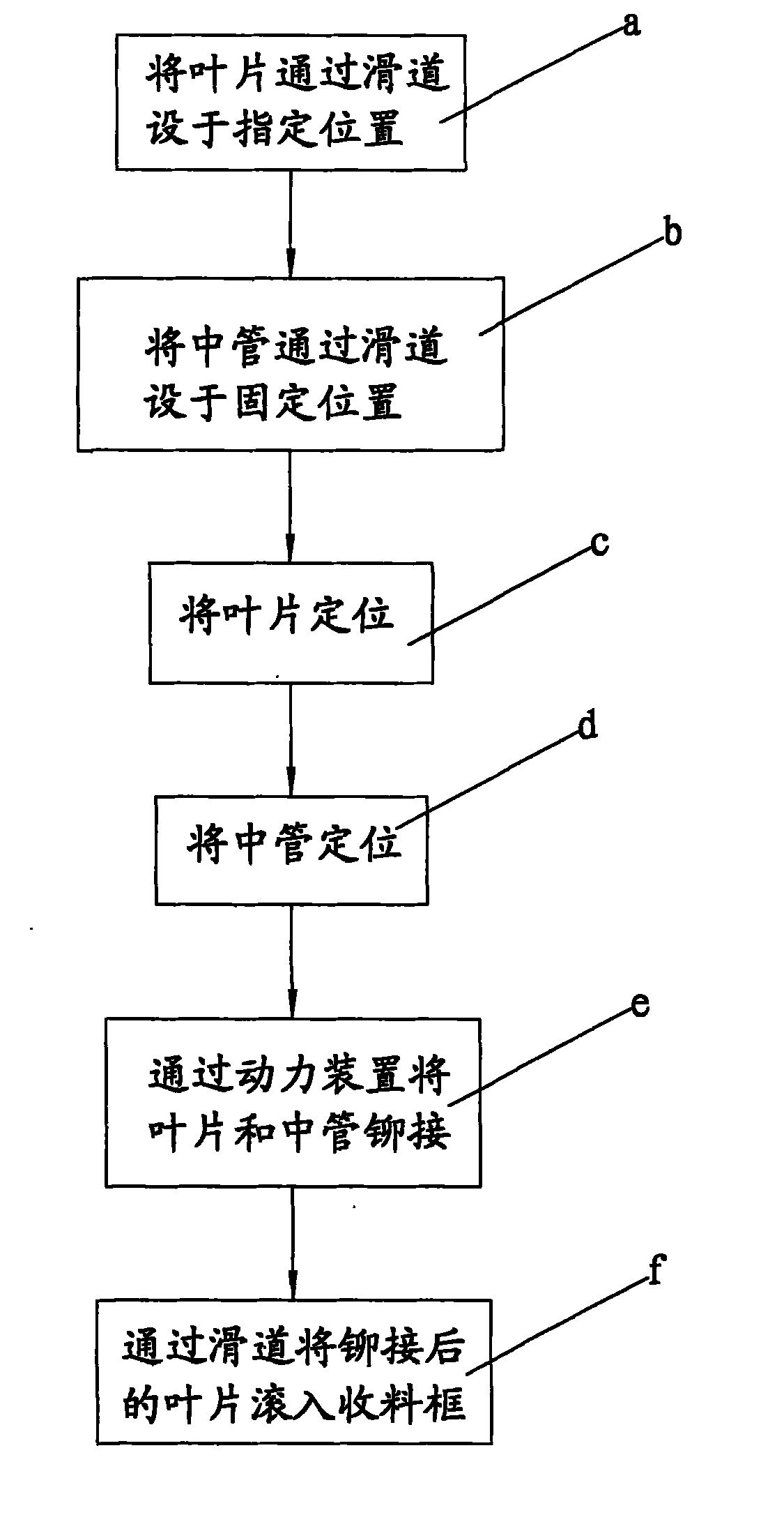
[0033] refer to figure 2 As shown, the present invention discloses an automatic riveting machine for hub blades, which includes a frame 1, upper and lower dies 3, 4 for pressing middle tubes, blade vibrating plate 5, middle tube vibrating plate 6, and blade jacking device 7, in:

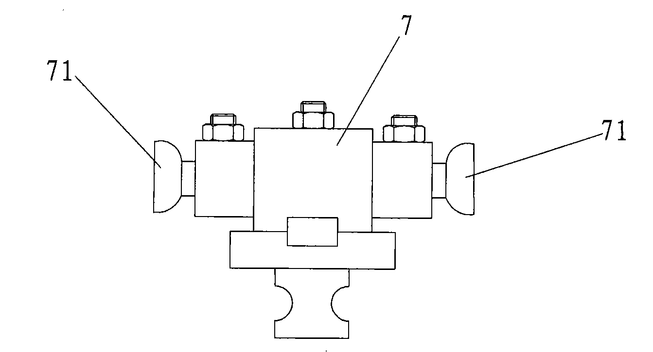
[0034] Cooperate Figure 4 , 5 As shown, the upper and lower molds 3 and 4 of the middle tube pressing are located on the upper and lower sides of the center of the frame 1, and cooperate with Figure 6 As shown, the blade vibrating disk 5 is symmetrically arranged on both sides of the frame, and it is connected to both sides of the blade ejector 7 of the frame 1 through the blade slideway 51. As shown in FIG. 8, the middle tube vibration plate 6 slides through the middle tube Road 61 links to each other with middle pipe pressing lower mold 4, and blade ejector 7 is also positioned on frame 1, and it can be controlled by inductor and solenoid valve (not shown in the figure), cooperates image 3 ...


PUM


Abstract

The invention discloses a hub blade automatic riveting machine comprising a stand, a medium tube, a medium tube pressing upper die, a middle tube pressing lower die, a blade vibrating disk, a middle tube vibrating disk and a blade ejector. The blade vibrating disk is connected with the stand through a blade slideway; the medium tube vibrating disk is connected with the medium tube pressing lower die through a medium slideway; the blade ejector fixes the blades on a blade positioning die on the stand; the medium tube pressing upper die and the medium tube pressing lower die are controlled through an air pressure cylinder; two blade positioning dies are externally provided with an oil cylinder respectively; and both sides of the blade ejector are provided with small roller cones. When the hub blade automatic riveting machine is used, the blades and the medium tube are respectively arranged in the blade vibrating disk and the medium tube vibrating disk; the blades enter into both sides ofthe blade ejector through the blade slideway; the medium tube enters into the medium tube pressing lower die through the medium tube slideway; the blades are positioned through the blade ejector, andthen the medium tube is positioned; and the oil cylinder moves towards the middle for riveting. The invention patent adopts the automatic operation, thereby reducing the work, lowering the cost, reducing the labor, and improving the quality and the stability of products.

Description

technical field [0001] The invention relates to the field of bicycle accessories, in particular to an automatic riveting machine for bicycle hub blades and a riveting method thereof. Background technique [0002] As we all know, the status of bicycles has gradually improved recently, and has progressed from the earliest means of transportation to leisure and sports tools. Its requirements for quality are very high, and the riveting of the existing bicycle hub blades is due to the number of holes in the blades and the staggered holes on both sides of the blades. , the blade must be placed in the positioning mold by hand, which is a manual operation method, which is to place the blade in the B and C grooves of the existing riveting machine, and place the middle tube on the middle tube pressing lower die, The left and right hands press the switch at the same time, and the middle tube and the blade start to rivet. This operation mode requires a lot of work, and is limited by the...

Claims


Application Information

Patent Timeline
Patent Type & Authority Patents(China)
IPC IPC(8): B21J15/14B21J15/20B21J15/24B21J15/42
Inventor 陈俊雄
Owner 久钰车料(昆山)有限公司
Learn More