
Three-stage regenerative multi-stream winding tube heat exchange equipment for cryogenic liquid nitrogen

A low-temperature liquid nitrogen, winding tube technology, applied in indirect heat exchangers, heat exchanger types, lighting and heating equipment, etc., can solve the complex heat exchange process, processing and manufacturing, inconvenient on-site installation and transportation, and pipeline leakage. And other issues

Inactive Publication Date: 2015-08-12
张周卫
View PDF4 Cites 0 Cited by
  • Summary
  • Abstract
  • Description
  • Claims
  • Application Information

AI Technical Summary

Problems solved by technology

At present, most low-temperature liquid nitrogen washing process systems adopt the overall heat exchange method, which connects the three-stage refrigeration process as a whole. The height of the heat exchanger can reach 60-80 meters, and the heat exchange efficiency has been significantly improved. The technological process is too complicated, and the volume of the heat exchange equipment is too large, which brings serious inconvenience to the processing and manufacturing, on-site installation and transportation, and once there are problems such as pipeline leakage, it is difficult to detect, and it is easy to cause the entire heat exchanger to be scrapped and the complete set of process equipment to stop production
Finally, the traditional method of replenishing liquid nitrogen is to directly inject the liquid nitrogen produced by the nitrogen production system into the contaminated nitrogen under the saturated state of 0.18MPa to reduce the entire reflux temperature and accelerate the start of the diffusion refrigeration process, but the vaporized nitrogen is discharged together with the contaminated nitrogen After the system is burned, it is discharged into the atmosphere, resulting in waste of nitrogen

Method used


Image

  • Three-stage regenerative multi-stream winding tube heat exchange equipment for cryogenic liquid nitrogen

Examples


Embodiment Construction

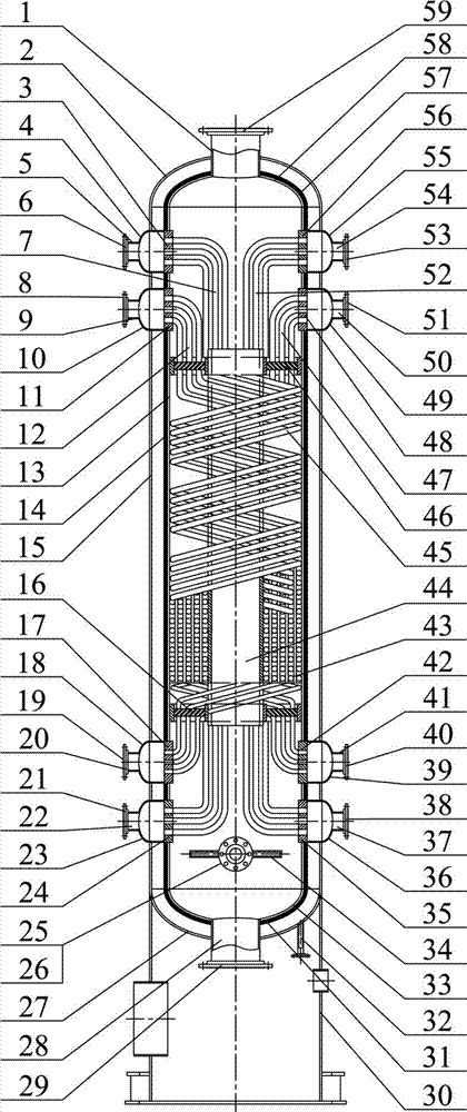
[0017] Processing and manufacturing of three-stage regenerative multi-stream winding tube heat exchange equipment for cryogenic liquid nitrogen, including three-stage high-pressure N 2 Inlet connecting pipe (1), third-level external pressure upper head (2), third-level nitrogen pollution outlet tube plate (3), third-level pollution nitrogen outlet pipe box (4), third-level pollution nitrogen outlet connection pipe (5), three-level Stage 1 nitrogen outlet flange (6), tertiary nitrogen winding tube bundle (7), tertiary purified gas inlet flange (8), tertiary purified gas inlet connecting pipe (9), tertiary purified gas inlet pipe box (10 ), three-stage purified gas inlet tube sheet (11), three-stage purified gas winding tube bundle (12), three-stage internal pressure cylinder (13), three-stage cylinder multi-layer vacuum insulation layer (14), three-stage external pressure Cylinder body (15), third-stage lower support ring (16), third-stage purified gas outlet tube plate (17), t...


PUM


Abstract

The invention mainly relates to the technical field of synthesis ammonia and low-temperature liquid nitrogen, and relates to the technology of a three-stage back heating multi-strand winding pipe type heat exchange device for the low-temperature liquid nitrogen. Through N2-H2 synthesis gas synthesized by H2 at the temperature of 191.5 DEG C below zero and the pressure of 1.8MPa and N2 at the temperature of 193.4 DEG C below zero and the pressure of 5.19MPa, through waste nitrogen N2-Ar-CO-CH4 at the temperature of 191.5 DEG C below zero and the pressure of 0.18MPa and through compensated high pressure LN2, N2 at the temperature of 127.2 DEG C below zero and the pressure of 5.7MPa is cooled to be N2 at the temperature of 188 DEG C below zero and the pressure of 5.6MPa, and purified gas H2-N2-CO-Ar-CH4 washed by low-temperature methanol is cooled to be purified gas at the temperature of 188.2 DEG C below zero and the pressure of 5.21MPa, namely, the incoming high-pressure N2 and the purified gas washed by the low-temperature methanol are cooled through cooling capacity back heating of the washed N2-H2 synthesis gas, high-pressure H2 and the waste nitrogen, and the temperature condition for washing the purified gas through the low-temperature liquid nitrogen is provided for a washing tower. The three-stage back heating multi-strand winding pipe type heat exchange device for the low-temperature liquid nitrogen is compact in structure and high in heat exchange efficiency and can be used for solving the technical problems of the three-stage six-strand four-bundle winding pipe type heat exchange for the low-temperature liquid nitrogen with the temperature ranging from 127.2 DEG C below zero to 193.4 DEG C below zero, and the low-temperature heat exchange efficiency of a low-temperature liquid nitrogen process system is improved.

Description

technical field [0001] The invention is mainly applied to the technical field of low-temperature liquid nitrogen process equipment for synthetic ammonia, and relates to the technology of three-stage six-stream four-tube bundle spirally wound tube heat exchange equipment for low-temperature liquid nitrogen. The -191.5 ℃, 1.8MPa H 2 , -193.4°C, 5.19MPa N flowing out of the top of the washing tower 2 —H 2 -191.5°C, 0.18MPa N of the synthesis gas and the top of the scrubber 2 —A r —CO—CH 4 Contaminated nitrogen, supplemented high-pressure LN 2 Cooling -127.2°C, 5.7MPa N 2 To -188℃, 5.6MPa LN 2 and cooling of H from the cryogenic methanol process 2 —N 2 —CO—A r —CH 4 Purify the gas to -188.2°C and 5.21MPa, that is, apply the washed N 2 —H 2 Syngas, high pressure H 2 And the cooling capacity of contaminated nitrogen is reheated and cooled to flow high-pressure N 2 , The purified gas washed by low-temperature methanol provides the washing tower with the temperature con...

Claims


Application Information

Patent Timeline
Patent Type & Authority Patents(China)
IPC IPC(8): F25J5/00F28D7/10
Inventor 张周卫汪雅红张小卫骆名军王小成赵刚吴金群薛佳幸
Owner 张周卫
Learn More