
A modular cabinet unit and combined cabinet

A modular and cabinet technology, applied in the direction of rack/frame structure, etc., can solve the problems of heavy design workload, low internal and external pressure bearing of the cabinet, high price, etc., to reduce workload, improve electronic equipment, high intensity effect

Active Publication Date: 2016-06-08
陕西海泰电子有限责任公司
View PDF6 Cites 0 Cited by
  • Summary
  • Abstract
  • Description
  • Claims
  • Application Information

AI Technical Summary

Problems solved by technology

Among them, the structural forms of sheet metal cabinets and FRP cabinets are shell thin plate support structures, which have the advantages of simple process form and low price, but the strength, rigidity and processing accuracy of the cabinet body are poor, and the internal load-bearing and external pressure of the cabinet body are low. , it is difficult to achieve double-layer or multi-layer precision stacking requirements; rotational molding cabinets are made of high-strength plastics through rotational molding, which has the advantages of beautiful shape, high processing precision, and double-layer or multi-layer stacking, but the price is high and the product Long development and processing cycles
[0003] The above different types of cabinets are currently unable to achieve modular design. Cabinet products of different specifications need to be customized and developed separately. The development cycle is long and the design workload is heavy, which is not conducive to the rapid response to customer delivery needs.

Method used


Image

  • A modular cabinet unit and combined cabinet
  • A modular cabinet unit and combined cabinet
  • A modular cabinet unit and combined cabinet

Examples


Embodiment Construction

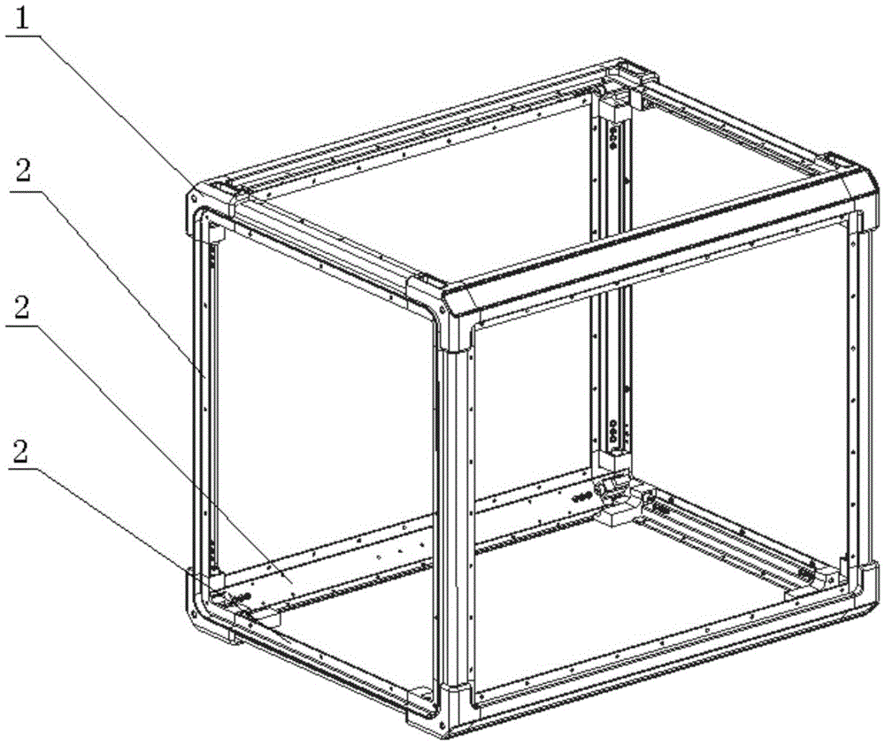
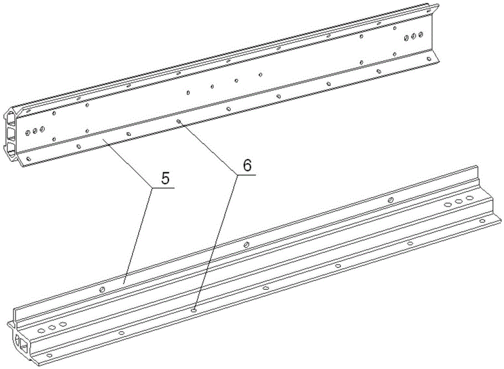
[0022] In the present invention, the corner block 1 and the beam 2 are spliced ​​into a cabinet frame as the main body of the cabinet to perform functions such as force bearing, positioning and installation. A complete cabinet unit consists of eight corner blocks 1 and twelve beams 2 . The corner block 1 and the beam 2 are connected by threads, welding, pins or combinations. The frame as a whole has high strength and rigidity. The effect of external forces on the cabinet. The cabinet cladding plate 8 can be freely assembled on the six sides of the frame according to specific application requirements.

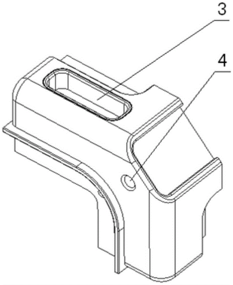
[0023] The size and shape of the corner block 1 are fixed, and a positioning groove 3 and a locking interface 4 are provided on the flat surface of the corner block 1 . When the cabinets are stacked in double or multiple layers, positioning pins can be installed on the positioning groove 3 of the corner block 1 to realize the precise stacking between the upper and lower layers...


PUM


Abstract

The invention provides a modularized cabinet unit and a combined-type cabinet. A body of the modularized cabinet unit is a cubic framework formed by twelve beams, angle blocks are arranged at the eight angles of the cubic framework respectively, and the abutting ends of every three corresponding beams are fixedly connected through the angle blocks. For each face of the cubic framework, inner edges formed by the corresponding beams, the corresponding angle blocks are provided with flange edges and inner peripheral connectors, and the flange edges and the inner peripheral connectors are used for installing surface plates. Locating grooves are further formed in the flat section faces of the angle blocks, and the locating grooves are used for realizing precision stacking of a plurality of modularized cabinet units through locating pins. Locking connectors are further arranged on the outer side faces of the corners of the angle blocks, and the locking connectors are used for realizing fixed connection of the modularized cabinet units through corresponding locking connecting pieces. The modularized cabinet unit has the advantages that only one type of cabinet unit needs to be developed for meeting the use requirements of different clients, and then product serialization can be realized simply through modularized variant design; designing and machining time is short, and the delivery requirements of the clients can be quickly responded.

Description

technical field [0001] The invention relates to a cabinet, in particular to a modular cabinet unit and a combined cabinet capable of realizing deformation design and processing of cabinet products. Background technique [0002] The current common cabinet products in the industry are generally sheet metal cabinets, rotational molding cabinets and glass fiber reinforced plastic cabinets. Among them, the structural forms of sheet metal cabinets and FRP cabinets are shell thin plate support structures, which have the advantages of simple process form and low price, but the strength, rigidity and processing accuracy of the cabinet body are poor, and the internal load-bearing and external pressure of the cabinet body are low. , it is difficult to achieve double-layer or multi-layer precision stacking requirements; rotational molding cabinets are made of high-strength plastics through rotational molding, which has the advantages of beautiful shape, high processing precision, and do...

Claims


Application Information

Patent Timeline
Patent Type & Authority Patents(China)
IPC IPC(8): H05K7/18
Inventor 郭恩全李成杨宏伟
Owner 陕西海泰电子有限责任公司
Learn More