Illuminating system of step scanning projection mask aligner

A step-scanning and lighting system technology, applied in the field of lighting systems, can solve problems such as small size of micro-slits, and achieve the effects of reducing processing difficulty, being easy to implement, and improving uniformity

Active Publication Date: 2013-11-27
BEIJING GUOWANG OPTICAL TECH CO LTD
View PDF7 Cites 6 Cited by
  • Summary
  • Abstract
  • Description
  • Claims
  • Application Information

AI Technical Summary

Problems solved by technology

Compared with the prior art [1], this system has lower requirements on the scanning speed of the slit, but there are still deficiencies, because the size of the micro slit is small, and the accuracy of scanning needs to be as high as micron or even submicron

Method used


Image

  • Illuminating system of step scanning projection mask aligner
  • Illuminating system of step scanning projection mask aligner
  • Illuminating system of step scanning projection mask aligner

Examples


Embodiment Construction

[0022] The present invention will be further described below in conjunction with the embodiments and accompanying drawings, but the protection scope of the present invention should not be limited thereby.

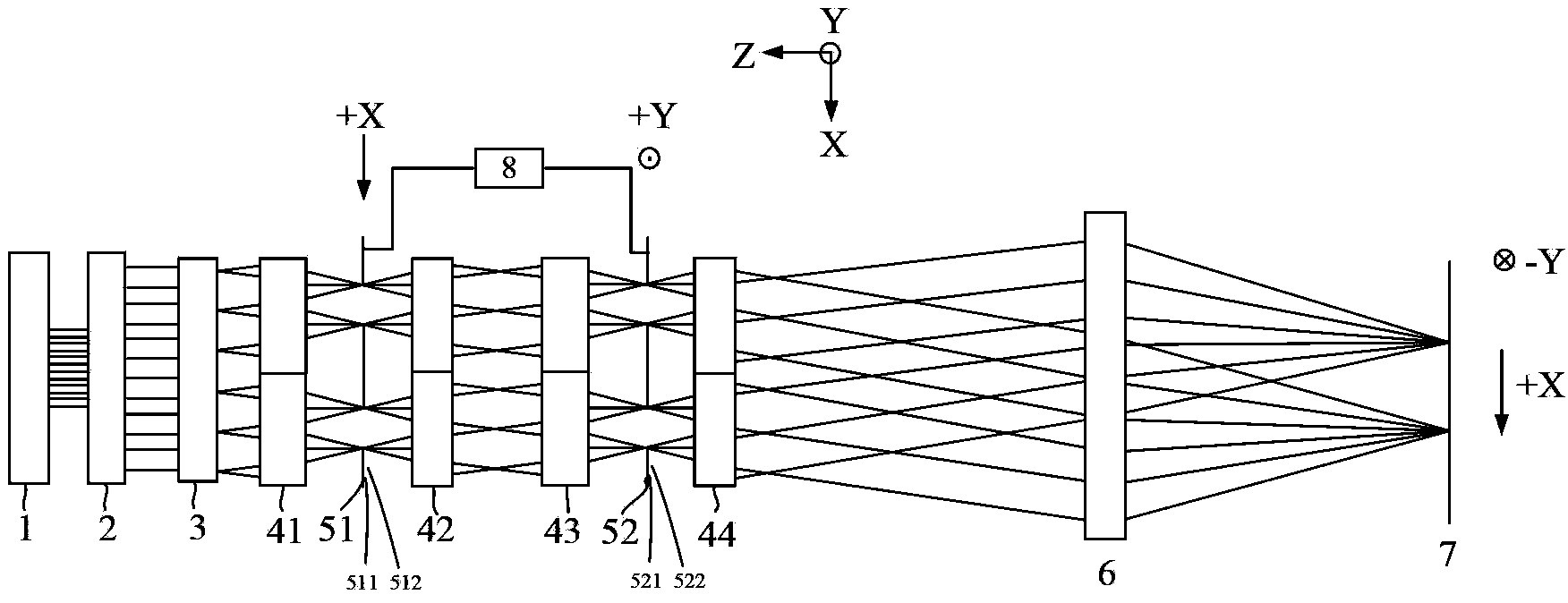
[0023] see first figure 1 , figure 1 It is a structural schematic diagram of the illumination system of the step-and-scan projection lithography machine of the present invention. It can be seen from the figure that the illumination system of the step-and-scan projection lithography machine of the present invention includes a light source 1, a pupil shaping unit 2, a field of view defining unit 3, a first lens array 41, a first slit array 51, and a second lens array 42 , the third lens array 43, the second slit array 52, the fourth lens array 44, the condenser lens 6 and the scanning drive unit 8, and its positional relationship is: the light emitted by the light source 1 passes through the pupil shaping unit 2 and the field of view defining unit successively 3. After the ...


PUM


Abstract

The invention relates to an illuminating system of a step scanning projection mask aligner. Along the beam propagation direction, the illuminating system comprises a light source, a pupil shaping unit, a viewing field defining unit, a first lens array, a first slit array, a second lens array, a third lens array, a second slit array, a fourth lens array, a collecting lens and a scanning driving unit. According to the illuminating system, the requirements on lens processing, slit scanning speed and slit scanning precision are reduced and can be easily realized.

Description

technical field [0001] The invention relates to a projection lithography machine, in particular to an illumination system for a step-and-scan projection lithography machine. technical background [0002] Optical lithography is the optical exposure process that transfers the pattern on the mask to the silicon wafer. According to different exposure methods, optical lithography can be divided into contact lithography, proximity lithography, step-and-repeat projection lithography, step-and-scan projection lithography, etc. Step and scan projection lithography can effectively improve the productivity of chips, and has become the mainstream lithography technology. [0003] The illumination system is one of the core components of a step-and-scan projection lithography machine. In order to accurately reproduce the fine patterns of different structures that may be on the mask onto the silicon wafer, the illumination system needs to form an illumination field with variable coherence...

Claims


Application Information

Patent Timeline
Patent Type & Authority Applications(China)
IPC IPC(8): G03F7/20
CPCG03F7/70058G03F7/70066G03F7/70075G03F7/7015
Inventor 曾爱军陈立群方瑞芳黄惠杰
Owner BEIJING GUOWANG OPTICAL TECH CO LTD
Why Eureka
Try Eureka