Sand-proofing valve
A valve body and valve cavity technology, applied in the field of sand-proof valves for oil wells, can solve problems such as easy damage to the valve seat and the soft sealing ring of the gate, easy entry of sand-containing impurities into the valve cavity, and inability of the pressure oil to seal. , to achieve the effect of good sealing, enhancing overall stability, enhancing tightness and sealing
- Summary
- Abstract
- Description
- Claims
- Application Information
AI Technical Summary
Problems solved by technology
Method used
Image

Examples
Embodiment 1
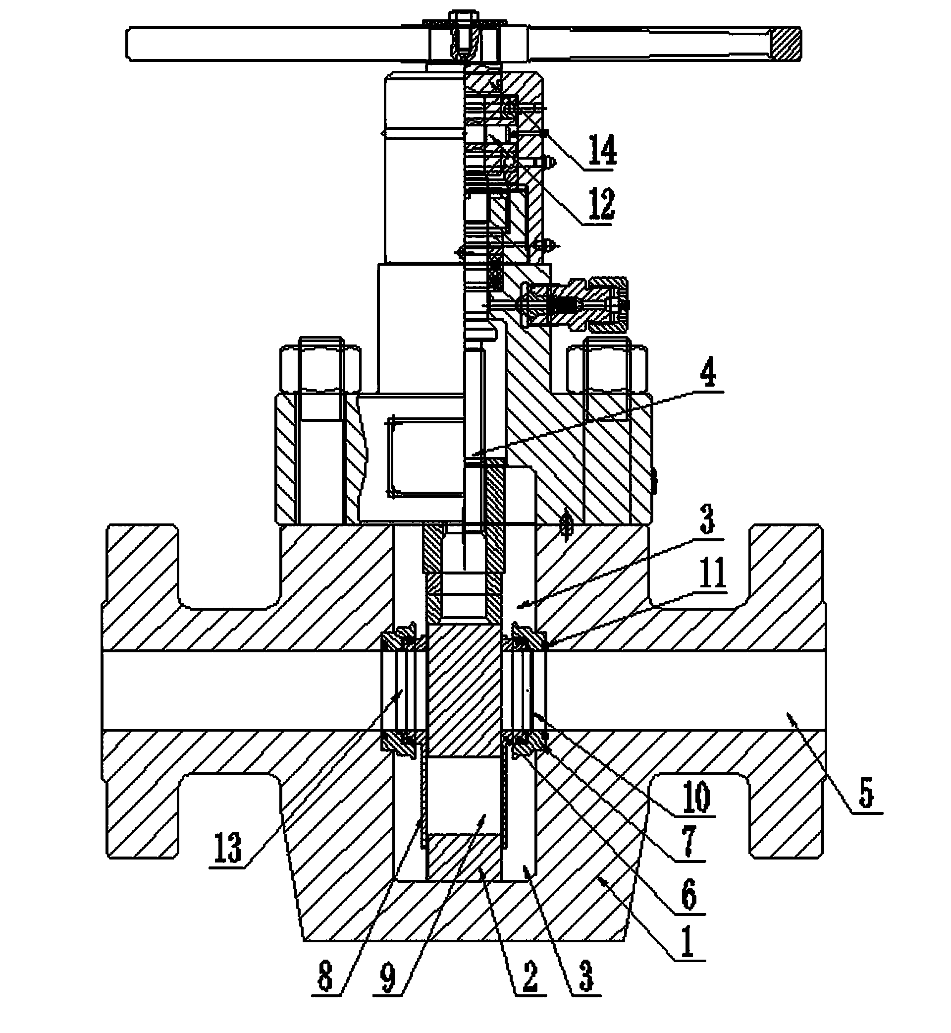
[0023] An anti-sand valve, comprising a valve body 1, a valve seat and a gate plate 2, the valve body 1 is provided with a valve cavity 3 and a medium circulation channel 5, the gate plate 2 is located in the valve cavity 3, and the valve cavity 3 is filled with sealing grease , the valve seat includes two inner valve seats 6 and two outer valve seats 7, the two outer valve seats 7 are embedded in the flow channel 5, and the two inner valve seats 6 are respectively embedded in the Inside the two outer valve seats 7, and the two inner valve seats 6 are fixedly arranged on both sides of the gate plate 2, an O-ring 11 is arranged between the outer valve seats 7 and the valve body 1, and the inner valve seats 6 An O-ring 11 is arranged between the outer valve seat 7, and the lower part of the two inner valve seats 6 extends vertically to form a sand-proof baffle 8 for closing the diversion hole 9 of the gate plate 2, preventing the 2 When the circulation passage 5 is closed, the s...
Embodiment 2
[0030] An anti-sand valve, comprising a valve body 1, a valve seat and a gate plate 2, the valve body 1 is provided with a valve cavity 3 and a medium circulation channel 5, the gate plate 2 is located in the valve cavity 3, and the valve cavity 3 is filled with sealing grease , the valve seat includes two inner valve seats 6 and two outer valve seats 7, the two outer valve seats 7 are embedded in the flow channel 5, and the two inner valve seats 6 are respectively embedded in the Inside the two outer valve seats 7, and the two inner valve seats 6 are fixedly arranged on both sides of the gate plate 2, an O-ring 11 is arranged between the outer valve seats 7 and the valve body 1, and the inner valve seats 6 An O-ring 11 is arranged between the outer valve seat 7, and the lower part of the two inner valve seats 6 extends vertically to form a sand-proof baffle 8 for closing the diversion hole 9 of the gate plate 2, preventing the 2 When the circulation passage 5 is closed, the s...
Embodiment 3
[0032]An anti-sand valve, comprising a valve body 1, a valve seat and a gate plate 2, the valve body 1 is provided with a valve cavity 3 and a medium circulation channel 5, the gate plate 2 is located in the valve cavity 3, and the valve cavity 3 is filled with sealing grease , the valve seat includes two inner valve seats 6 and two outer valve seats 7, the two outer valve seats 7 are embedded in the flow channel 5, and the two inner valve seats 6 are respectively embedded in the Inside the two outer valve seats 7, and the two inner valve seats 6 are fixedly arranged on both sides of the gate plate 2, an O-ring 11 is arranged between the outer valve seats 7 and the valve body 1, and the inner valve seats 6 An O-ring 11 is arranged between the outer valve seat 7, and the lower part of the two inner valve seats 6 extends vertically to form a sand-proof baffle 8 for closing the diversion hole 9 of the gate plate 2, preventing the 2 When the circulation passage 5 is closed, the sa...
PUM
 Abstract
Description
Claims
Application Information
 - R&D
- Intellectual Property
- Life Sciences
- Materials
- Tech Scout
- Unparalleled Data Quality
- Higher Quality Content
- 60% Fewer Hallucinations
Browse by: Latest US Patents, China's latest patents, Technical Efficacy Thesaurus, Application Domain, Technology Topic, Popular Technical Reports.
© 2025 PatSnap. All rights reserved.Legal|Privacy policy|Modern Slavery Act Transparency Statement|Sitemap|About US| Contact US: help@patsnap.com