Fluid end device of plunger pump

A technology of hydraulic end and plunger pump, which is applied to the components of pumping devices for elastic fluid, pump components, and variable displacement pump components, etc., can solve the problems of reduced service life, increased weight, and easy damage. , to achieve the effect of reducing the closing lag angle, improving the volumetric efficiency, and reducing the clearance volume

Active Publication Date: 2013-11-27
INST OF SINOPEC OILFIELD EQUIP CORP +1
View PDF6 Cites 4 Cited by
  • Summary
  • Abstract
  • Description
  • Claims
  • Application Information

AI Technical Summary

Problems solved by technology

First of all, the suction valve and discharge valve of the split valve group are arranged separately, with many parts and complex structure, which is not easy to disassemble and assemble, which makes maintenance and replacement inconvenient; secondly, there are intersecting holes in the pressure alternating chamber of the pump head body, and the , under frequent alternating pressure, the parts with high stress on the pump head body are easy to be damaged, and its service life is easily reduced; thirdly, a large clearance volume will be formed between the suction valve, discharge valve and plunger, and the volumetric efficiency There is still room for improvement
[0004] The existing combined valve fluid end has the following disadvantages. First, the flow area of ​​the combined valve group is small, and the lift of the valve plate needs to be increased in order to increase the flow rate, which leads to the closing speed, acceleration, impact force, and noise of the valve plate. And the closing lag angle will increase, which seriously affects the service life and volumetric efficiency of the valve group; second, the various parts of the fluid end are connected by multiple sets of bolts, which is inconvenient to disassemble; third, the axial dimension of the combined valve is large, resulting in Large pump head body size and increased weight

Method used


Image

  • Fluid end device of plunger pump
  • Fluid end device of plunger pump
  • Fluid end device of plunger pump

Examples


Embodiment Construction

[0030] In order to have a clearer understanding of the technical features, purposes and effects of the present invention, the specific implementation manners of the present invention will now be described in detail with reference to the accompanying drawings.

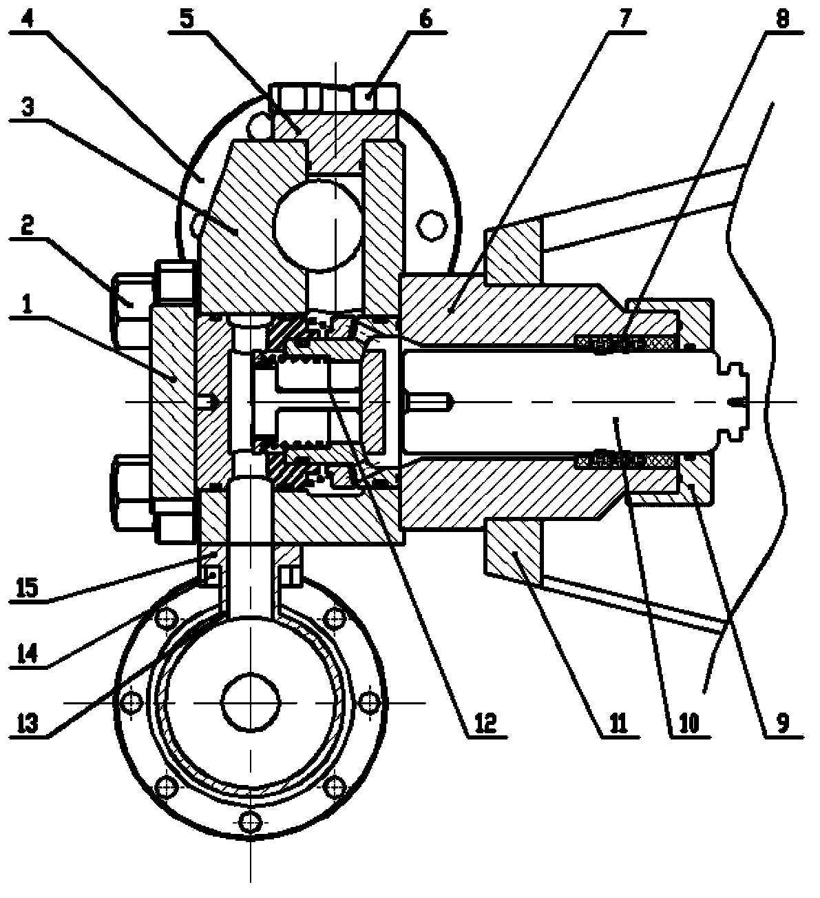
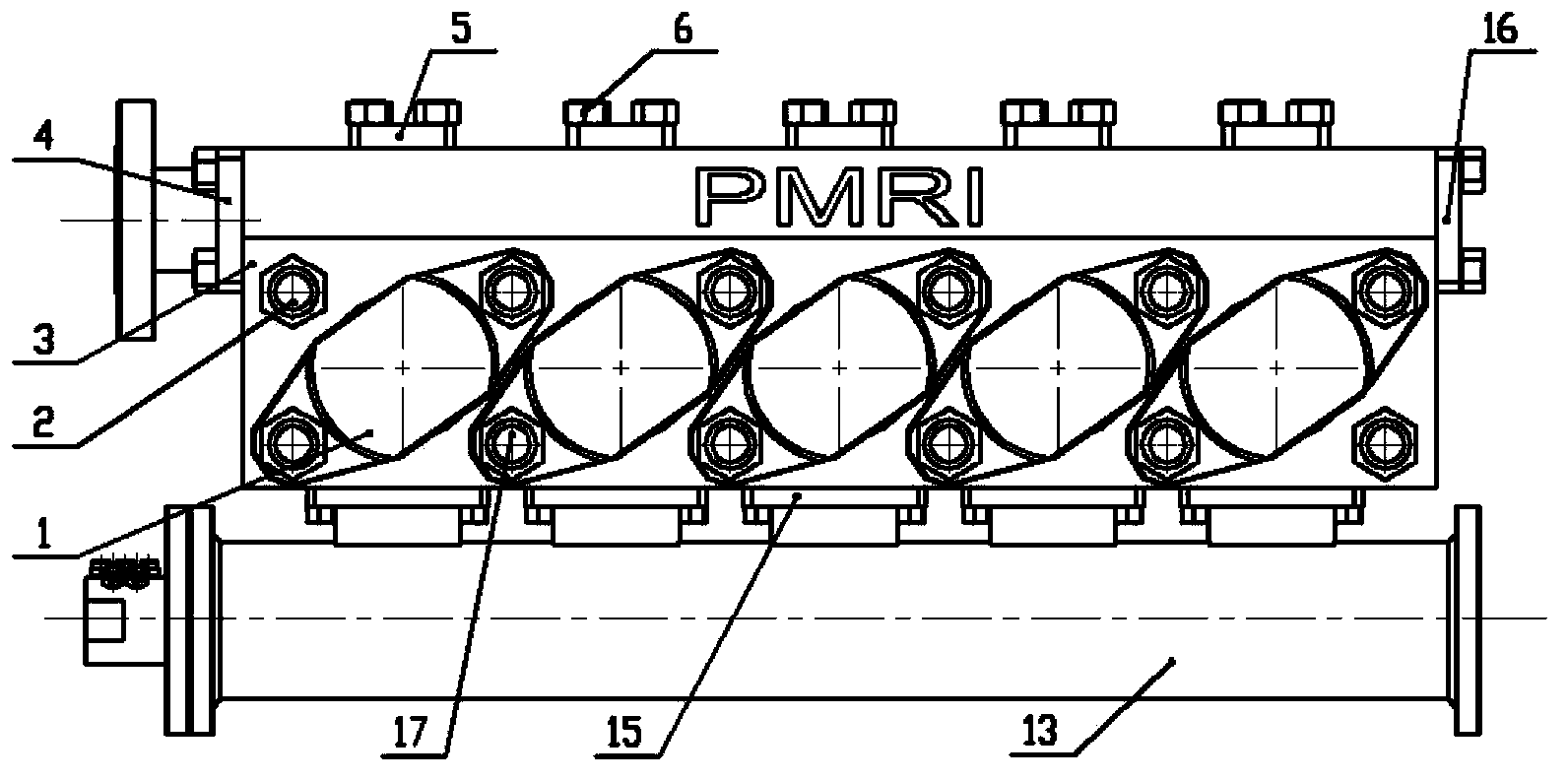
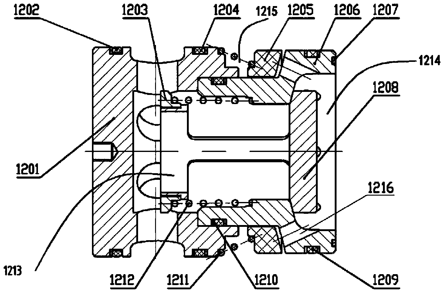
[0031] Such as Figure 1-Figure 4 As shown, the hydraulic end device of the plunger pump of the present invention includes a pump head body 3 , a plug-in combination valve 12 , a packing box 7 and a plunger 10 .

[0032] The pump head body 3 is provided with a suction port and a discharge port. In this embodiment, a suction pipe 13 is provided at the suction port, and the liquid suction pipe 13 is connected to the suction port through a suction flange 15 , and the suction flange 15 is fixed on the pump head body 3 through a nut 14 . One end of the discharge port is provided with a discharge flange 4, and the other end of the discharge port is provided with a discharge pipe plug 16. The discharge flange 4 and the discha...


PUM


Abstract

The invention relates to a fluid end device of a plunger pump. The fluid end device of the plunger pump comprises a pump head body (3), a cartridge combination valve (12), a stuffing box (7) and a plunger (10). The pump head body (3) is provided with a suction inlet and an exhaust outlet, and the cartridge combination valve (12) is arranged inside the pump head body (3); a liquid inlet cavity (1213) communicated with the suction inlet and a liquid outlet cavity (1215) communicated with the exhaust outlet are formed between the pump head body (3) and the cartridge combination valve (12); the end surface of the stuffing box (7) is closely adhered to the pump head body (3), and the plunger (10) can move inside the stuffing box (7) in a reciprocating mode; the cartridge combination valve (12) comprises a pressing sleeve (1201), a valve core (1206), a suction valve (1208) and a discharge valve (1205). The fluid end device of the plunger pump improves the overflowing performance of the combination valve and the guide performance between the suction valve and the valve core and meanwhile is compact and simple in structure; the pump head body is small in size; the fluid end device of the plunger pump is high in volume efficiency, easy to assemble and disassemble and rapid in maintenance and replacement.

Description

technical field [0001] The invention relates to the field of reciprocating plunger pumps, in particular to a liquid end device of a plunger pump. Background technique [0002] The structure of the reciprocating plunger pump consists of two parts, one is the fluid end, the other is the power end, and the fluid end is the working part of the reciprocating high-pressure plunger pump, which is used to transport liquid and convert mechanical energy into liquid pressure energy. At present, the common hydraulic end of the plunger pump has a valve group divided into a split valve group and a combined valve group. [0003] The hydraulic end layout of the split valve group includes traditional "L" type, reverse "L" type, "V" type, "Y" type, and "+" type liquid end. First of all, the suction valve and discharge valve of the split valve group are arranged separately, with many parts and complex structure, which is not easy to disassemble and assemble, which makes maintenance and replac...

Claims


Application Information

Patent Timeline
Patent Type & Authority Applications(China)
IPC IPC(8): F04B53/00F04B53/10
Inventor 张策周向东代琼曦吴刚钱伟强
Owner INST OF SINOPEC OILFIELD EQUIP CORP
Why Eureka
Try Eureka