
Combined cutter and pipe cutting method

A cutting knife and blade technology, which is applied in the pipe cutting machine double-knife combined cutting knife, and the pipe cutting field of the above-mentioned combined cutting knife, can solve the problems of iron filings splashing, low processing efficiency, and low service life of saw blades, etc.

Inactive Publication Date: 2013-11-20
FAURECIA QINGDAO EXHAUST SYST
View PDF4 Cites 1 Cited by
  • Summary
  • Abstract
  • Description
  • Claims
  • Application Information

AI Technical Summary

Problems solved by technology

[0003] When using the circular saw blade pipe cutting machine to cut the pipe fittings, the disadvantages are: 1. Low processing accuracy: because the saw blade of the pipe cutting machine has a fixed gap, the saw blade swings left and right when the saw blade cuts up, so the pipe fittings are cut The length accuracy is not well controlled, and the general accuracy is controlled at ±0.5mm, which seriously affects the product quality; 2. The cut surface is seriously inclined: due to the deviation of the fixed position of the fixture and the lifting of the pipe by the saw blade, the section of the cut pipe is cut Inclination and poor verticality affect the welding quality of subsequent products; 3. The life of the saw blade is low and the cost of cutting pipes is high: each saw blade cuts 600-800 pieces of pipe fittings, and it needs to be re-grinded to cut one pipe on average. 0.36 yuan per piece; 4. Long cutting time and low processing efficiency: use a saw blade to cut, and the average time for each pipe cutting is 26S, and the time is too long to meet the production demand; 5. The pipe cutting noise is loud, and the chips are not easy to handle: the saw blade The maximum noise during cutting can reach 82 decibels, which seriously affects the health of the body, and the iron filings are scattered everywhere, which is difficult to collect and handle

Method used


Image

  • Combined cutter and pipe cutting method
  • Combined cutter and pipe cutting method
  • Combined cutter and pipe cutting method

Examples


Embodiment Construction

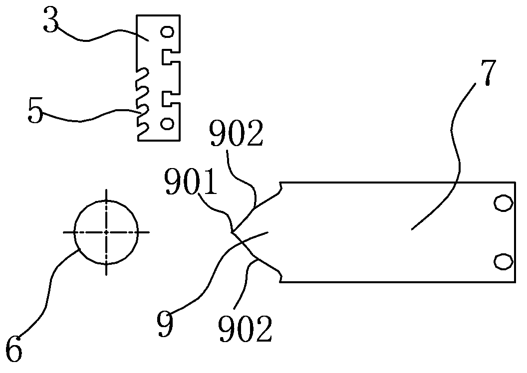
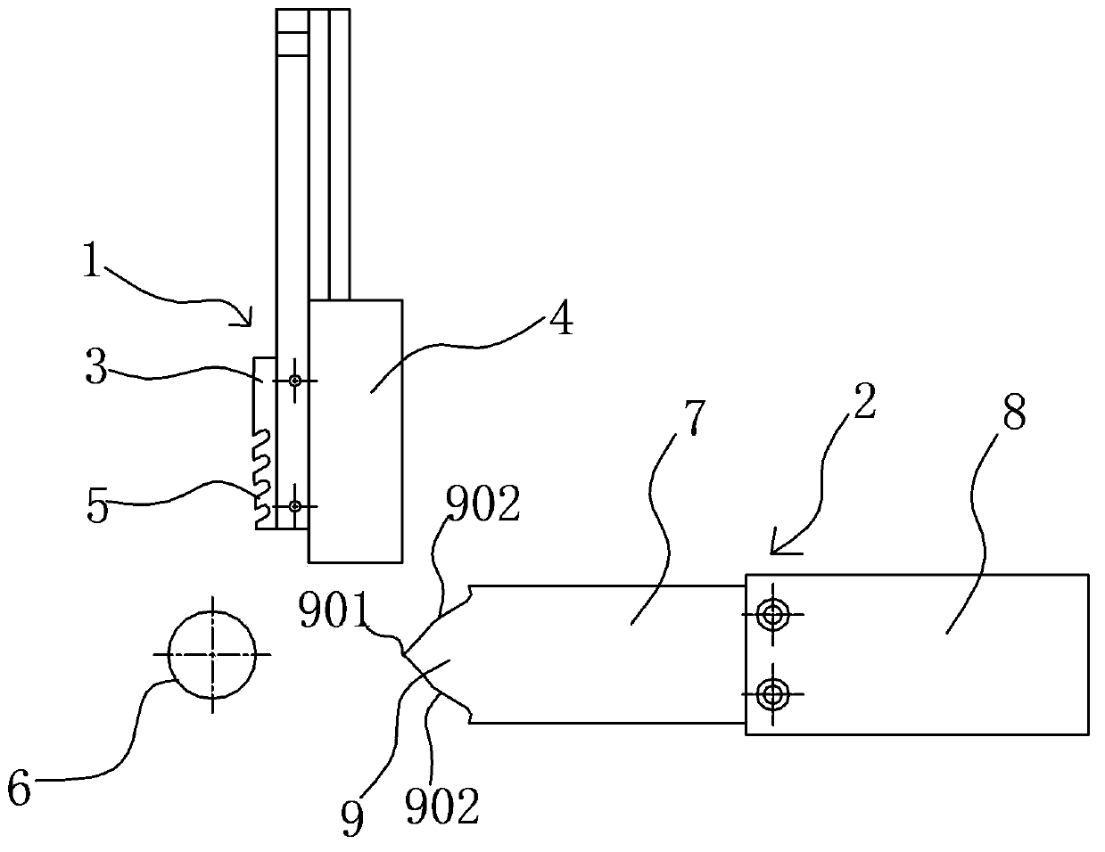
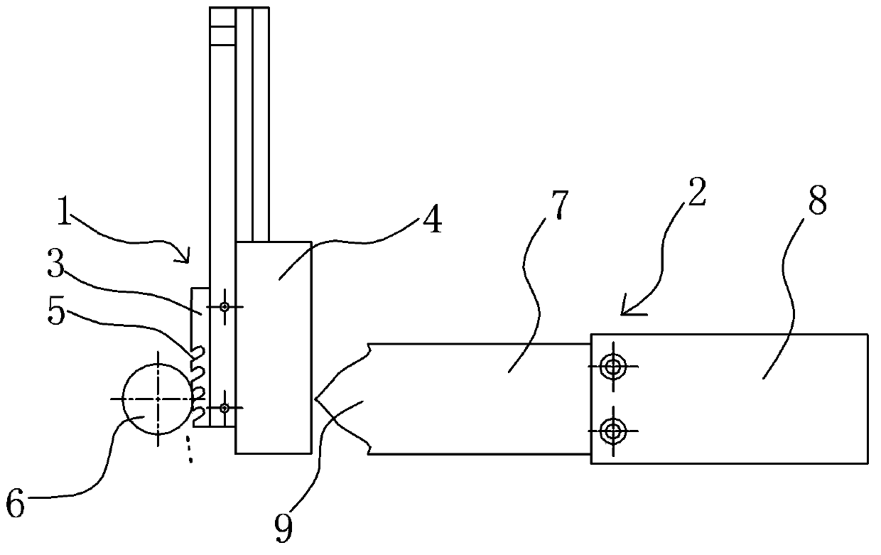
[0023] With reference to the accompanying drawings, a combined cutter includes a vertical cutter 1 and a horizontal cutter 2, and the vertical cutter 1 and the horizontal cutter 2 act alternately. The vertical cutter 1 includes a vertical blade 3 and a vertical fixing seat 4, and the vertical blade 3 and the vertical fixing seat 4 are fixed together by bolts. The vertical blade 3 is a long broach, and the lower left side of the vertical blade 3 is provided with sawtooth 5. The function of the vertical blade 3 is to saw a groove in the pipe fitting 6 in the vertical direction, so as to reduce the cutting of the horizontal cutter 2 behind. resistance to prevent the pipe fitting 6 from sinking and deforming. The horizontal cutter 2 comprises a horizontal blade 7 and a horizontal fixed seat 8, and the horizontal blade 7 and the horizontal fixed seat 8 are also fixed by bolts. The left end of the horizontal blade 7 is a cutting end 9, and the cutting end 9 includes a tip 901. An a...


PUM


Abstract

The invention discloses a combined cutter which comprises a first blade and a second blade which operate alternatively. Sawteeth for scratching pipe fittings are arranged on the first blade. One end of the second blade is a cutting end for penetrating breakages of the pipe fittings and cutting off the pipe fittings. The cutting end is in the shape of a peach heart tip. The first blade is perpendicularly arranged while the second blade is horizontally arranged. Two blades are combined and cooperate with each other to cut off the pipe fittings, so that processing accuracy is improved, production cost is reduced, cutting-off time is shortened, pipe cutting noise is reduced, and generation of scrap iron during pipe cutting is reduced.

Description

technical field [0001] The invention belongs to the field of machine tool processing tools, and specifically relates to a pipe cutting machine with a double-knife combined cutter, which is mainly suitable for cutting hot-end pipe fittings and cold-end pipe fittings of automobile exhaust pipes. At the same time, the invention also relates to the above-mentioned combined cutter pipe cutting method. Background technique [0002] At present, in the pipe cutting processing industry of automobile exhaust pipe fittings, the main pipe cutting method is to use a circular saw blade for cutting. When cutting, the circular saw blade rises slowly, and its upper serrations separate the pipe piece by piece into pieces of iron pins, and finally cut off the pipe piece. Then the circular saw blade slowly descends and returns to its original position. [0003] When using the circular saw blade pipe cutting machine to cut the pipe fittings, the disadvantages are: 1. Low processing accuracy: b...

Claims


Application Information

Patent Timeline
IPC IPC(8): B23D79/00
Inventor 胡瑞祥张乐峰潘昌
Owner FAURECIA QINGDAO EXHAUST SYST
Learn More