
Method for displaying M/A island structures inside pipeline steel

A display method and technology for pipeline steel, which are applied in measuring devices, instruments, and optical devices, etc., can solve the problems of complicated operation and expensive microscope, and achieve the effect of simple operation and shortened corrosion time.

Active Publication Date: 2013-11-13
BC P INC CHINA NAT PETROLEUM CORP +1
View PDF6 Cites 9 Cited by
  • Summary
  • Abstract
  • Description
  • Claims
  • Application Information

AI Technical Summary

Problems solved by technology

However, its operation is complicated, and it needs to be used with laser confocal microscope, and the microscope is relatively expensive, which belongs to high-end and unconventional equipment

Method used


Image

  • Method for displaying M/A island structures inside pipeline steel
  • Method for displaying M/A island structures inside pipeline steel
  • Method for displaying M/A island structures inside pipeline steel

Examples


Embodiment 1

[0053] Step 1, pipeline steel sample preparation

[0054] Use 120#, 360#, 600#, 800#, 1000# metallographic water sandpaper for rough grinding and fine grinding for X70 samples respectively. After replacing the fine sandpaper, the grinding direction should be 90° to the previous direction until the previous grinding marks are worn off. Afterwards, the samples were polished with 2.5 μm and 1.5 μm diamond spray polishing agents for 3 minutes respectively. At this time, the test surface of the sample becomes a mirror surface without scratches.

[0055] Step 2, preparation of coloring reagent

[0056]在烧杯中将100ml蒸馏水中加入0.95g偏重亚硫酸钠;100ml无水乙醇中加入3.6g苦味酸和0.6g氢氧化钠。将两种溶液3:2混合并加热至50℃,保温2min。在加热过程中用玻璃棒进行搅拌使其完全溶解且充分反应,所得溶液即为着色试剂。

[0057] 步骤三,M / A岛的腐蚀显示

[0058] 将试样采用2%的硝酸酒精溶液腐蚀5s左右后用酒精洗净吹干。此时金相观察应为轻度腐蚀。将步骤二中所制备的着色试剂加热至50℃,将试样放入其中浸泡200s后用酒精洗净吹干。

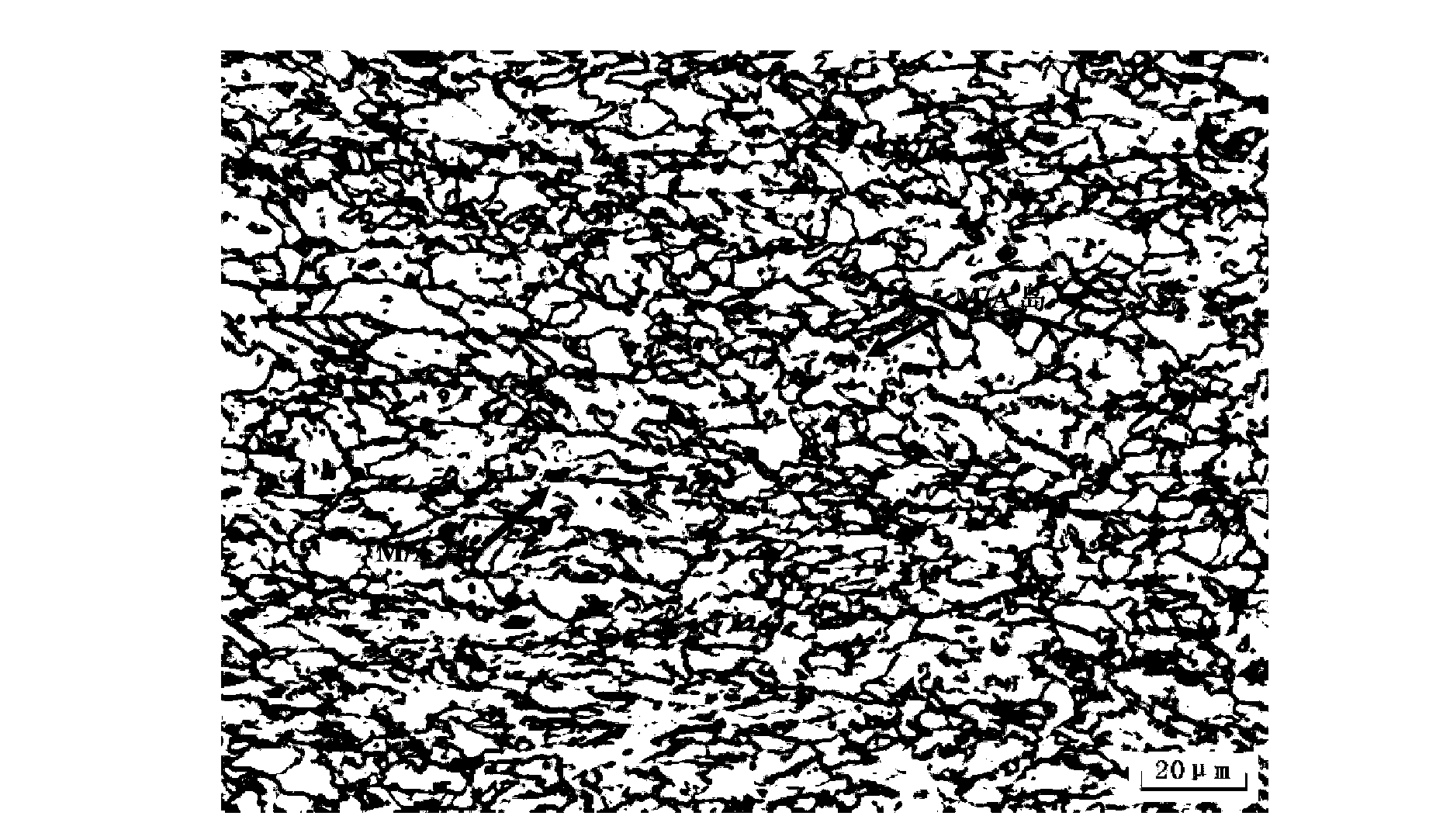
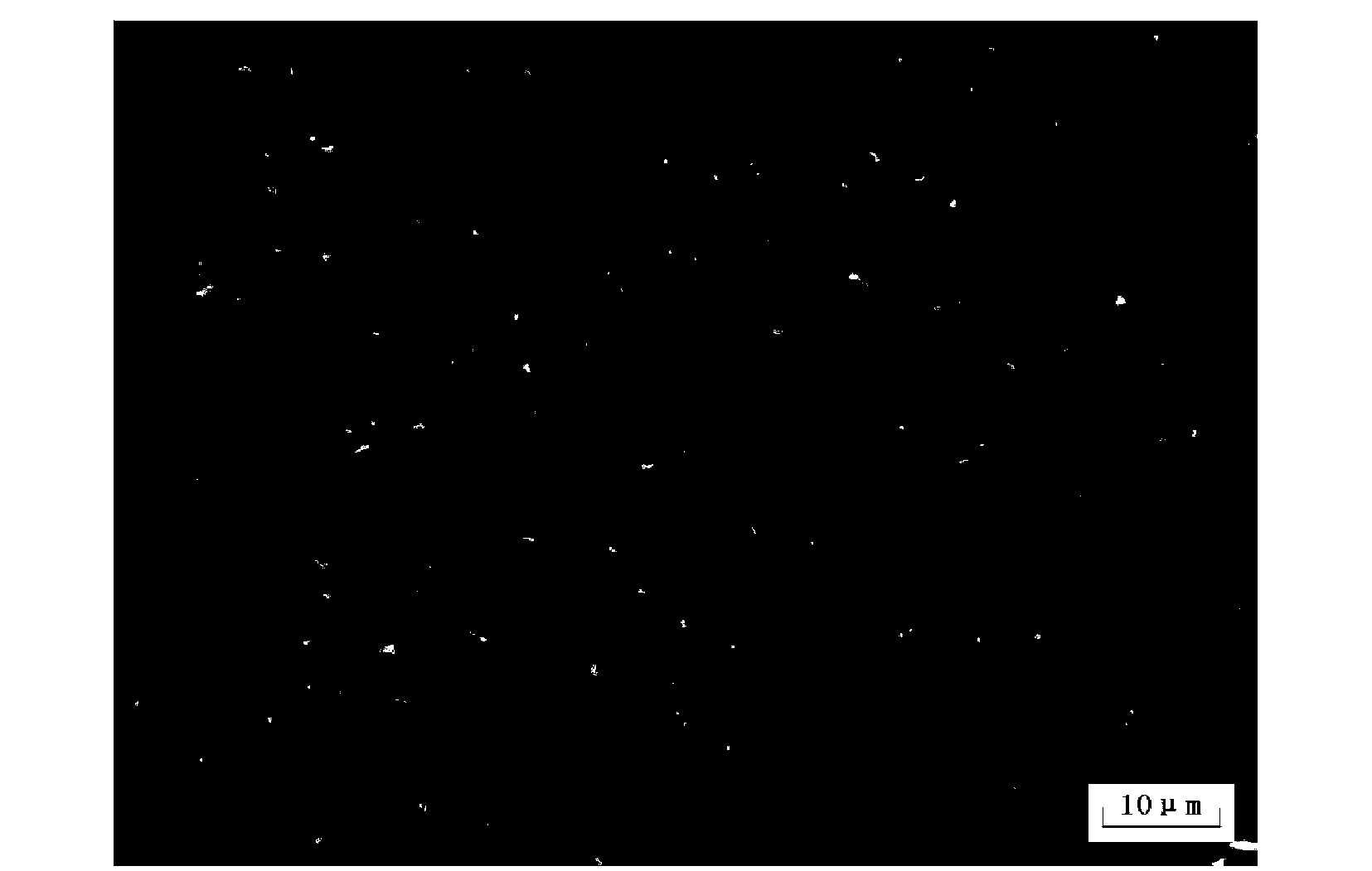
[0059] 经上述对管线钢试样进行处理后,将其放置金相显微镜下进行观察,如 figure 2 所示,M / A岛呈现出亮白色M / A岛,与周围组织灰度差明显。

Embodiment 2

[0061] 步骤一,管线钢试样制备

[0062] 对X80试样分别使用120#、360#、600#、800#、1000#金相水砂纸进行粗磨、细磨。更换细砂纸后的打磨方向要与上道方向成90°,直到上道磨痕磨掉为止。之后对试样分别使用2.5μm、1.5μm的金刚石喷雾抛光剂各抛光5min。此时试样的检验面成镜面且无划痕。

[0063] 步骤二,着色试剂的制备

[0064] 在烧杯中将100ml蒸馏水中加入1g偏重亚硫酸钠;100ml无水乙醇中加入3.65g苦味酸和0.65g氢氧化钠。将两种溶液3:2混合并加热至50℃,保温3min。在加热过程中用玻璃棒进行搅拌使其完全溶解且充分反应,所得溶液即为着色试剂。

[0065] 步骤三,M / A岛的腐蚀显示

[0066] 将试样采用2%的硝酸酒精溶液腐蚀5s左右后用酒精洗净吹干。此时金相观察应为轻度浸蚀。将步骤二中所制备的着色试剂加热至50℃,将试样放入其中浸泡180s后用酒精洗净吹干。

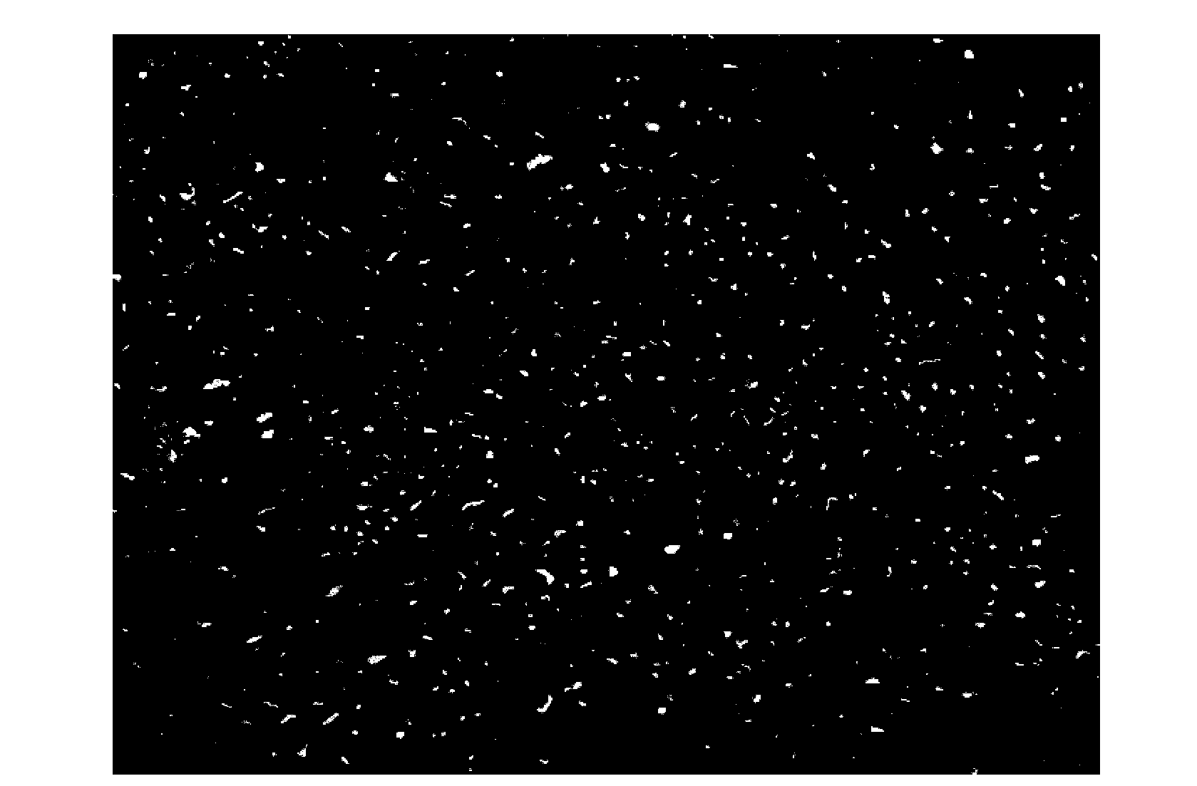
[0067] 经上述对管线钢试样进行处理后,将其放置金相显微镜下进行观察,如 image 3 所示,M / A岛呈现出亮白色M / A岛,与周围组织灰度差明显。

Embodiment 3

[0069] 步骤一,管线钢试样制备

[0070] 对X80试样分别使用120#、360#、600#、800#、1000#金相水砂纸进行粗磨、细磨。更换细砂纸后的打磨方向要与上道方向成90°,直到上道磨痕磨掉为止。之后对试样分别使用2.5μm、1.5μm的金刚石喷雾抛光剂各抛光5min。此时试样的检验面成镜面且无划痕。

[0071] 步骤二,着色试剂的制备

[0072] 在烧杯中将100ml蒸馏水中加入1.05g偏重亚硫酸钠;100ml无水乙醇中加入3.7g苦味酸和0.7g氢氧化钠。将两种溶液3:2混合并加热至50℃,保温3min。在加热过程中用玻璃棒进行搅拌使其完全溶解且充分反应,所得溶液即为着色试剂。

[0073] 步骤三,M / A岛的腐蚀显示

[0074] 将试样采用4%的硝酸酒精溶液腐蚀5s左右后用酒精洗净吹干。此时金相观察应为轻度浸蚀。将步骤二中所制备的着色试剂加热至55℃,将试样放入其中浸泡240s后用酒精洗净吹干。

[0075] 经上述对管线钢试样进行处理后,将其放置金相显微镜下进行观察,如 Figure 4 所示,M / A岛呈现出亮白色M / A岛,与周围组织灰度差明显。


PUM


Abstract

The invention discloses a method for displaying M / A island structures inside pipeline steel, and belongs to the technical field of metallographic phase structure displaying and quantifying. Specifically, A sample is grinded and polished into a mirror face to be used later; 1g sodium metabisulfite is added into 100ml distilled water inside a beaker; 3.65g picric acid and 0.65g sodium hydroxide are added into 100ml absolute ethyl alcohol; the two kinds of solutions are mixed according to the proportion of 3: 2 and are heated and stirred to obtain the improved staining reagent; 2-4% of nitric acid ethyl alcohol solution is used for slightly corroding the prepared sample, and the sample is placed into the staining reagent to be immersed for 120-240 seconds and then is washed clean through the ethyl alcohol and is blown to be dried; an M / A island presents bright white and is very different from the surrounding structures in the gray level. The method is easy to operate, the corrosion time is short, and the area content, the size, the shape and other characteristic parameters of the M / A island in the structures can be fast, accurately and quantificationally analyzed through metallographic phase software.

Description

technical field [0001] The invention relates to the technical field of metallographic structure display and quantification, and specifically provides a method for displaying the M / A island structure in pipeline steel. Background technique [0002] The strength and toughness of steel are closely related to its microstructure. With the improvement of strength and toughness, the microstructure of pipeline steel gradually evolves from the initial ferrite-pearlite (PF-P) type to granular bainite (GB) type. The remarkable feature of the granular bainite structure is the distribution of martensite and retained austenite (M / A) islands on the high-density dislocation iron matrix. M / A islands are an important component of granular bainite. As the second hard phase in the microstructure, the characteristic parameters such as the area content, size, and shape of M / A islands have a great influence on the strength and toughness of pipeline steel. Therefore, the quantitative analysis of...

Claims


Application Information

Patent Timeline
IPC IPC(8): G01B11/28G01B11/02G01B11/24
Inventor 仝珂李鹤李金凤宋娟卫尊义
Owner BC P INC CHINA NAT PETROLEUM CORP
Learn More