
Auxiliary power supply process by an auxiliary power group and corresponding architecture

A technology of power supply and supply method, applied in the field of auxiliary power supply structure, capable of solving problems such as strong maintenance constraints and unnecessary flight loads

Inactive Publication Date: 2013-11-13
MICROTURBO SA
View PDF7 Cites 7 Cited by
  • Summary
  • Abstract
  • Description
  • Claims
  • Application Information

AI Technical Summary

Problems solved by technology

[0008] The main drawback of known devices is the unnecessary flight load of such devices and the strong maintenance constraints, especially for RATs

Method used


Image

  • Auxiliary power supply process by an auxiliary power group and corresponding architecture
  • Auxiliary power supply process by an auxiliary power group and corresponding architecture
  • Auxiliary power supply process by an auxiliary power group and corresponding architecture

Examples


Embodiment Construction

[0026] In the present description, the terms "upstream" and "downstream" relate to positions depending on the direction of fuel circulation. The same notes on different figures refer to the same parts as defined in the corresponding paragraphs of the present specification.

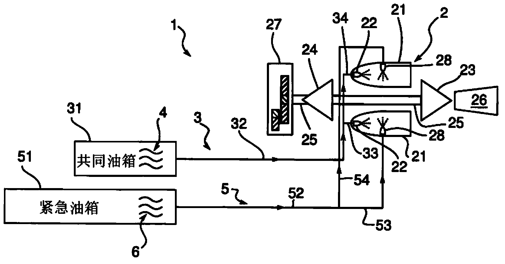
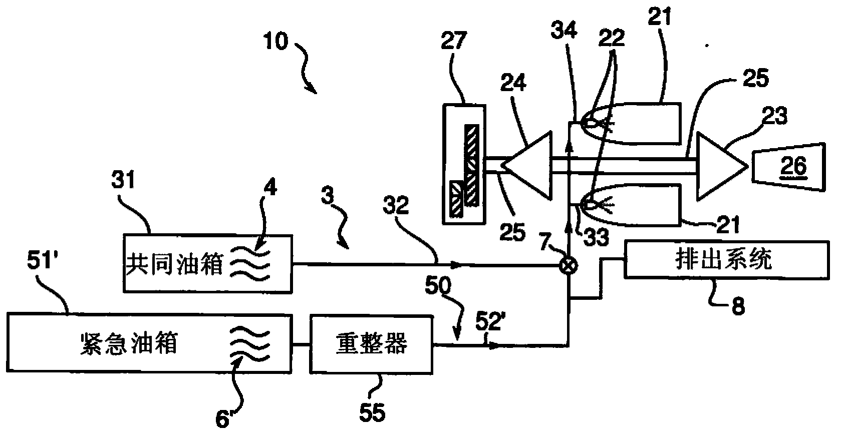
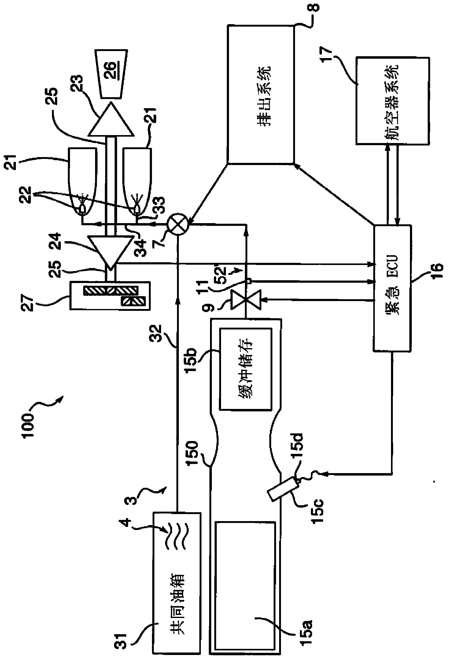
[0027] refer to figure 1 As shown in FIG. 2 , an exemplary structure 1 for providing auxiliary power to an aircraft comprises an APU unit 2 and a basic circuit 3 for supplying fuel 4 in the APU unit 2 . This circuit includes a fuel storage tank 31 , ie kerosene in the embodiment, for common supply to the engine of the aircraft (not shown) and the APU unit 2 . It also comprises a primary conduit 32 for the common fuel circulation, and secondary conduits 33 , 34 for injecting this fuel 4 into the combustion chamber 21 of the APU device 2 . This injection is effected by injector 22 .

[0028] The APU unit 2 includes a gas generator present in a drive turbine 23 , via a transmission shaft 25 for an air comp...


PUM


Abstract

The method involves providing non-propelling power to consumers of an aircraft from a storage reservoir (31) of fuel (4) common to an engine of the aircraft and an auxiliary power unit (APU) (2), in a main mode. A basic circulation of the fuel is provided to a combustion chamber (21) of the APU. The APU is used in an emergency mode to provide backup power to vital systems of the aircraft. The chamber is supplied by emergency fuel (6) from an emergency tank (51) according to independent and separated circulation in a part in connection with a primary pipe (52). The fuel is kerosene, and the emergence fuel (6) is hydrogen directly stored in a solid, liquid or gas state in the specific source. An independent claim is also included for power supply architecture.

Description

technical field [0001] The present invention relates to a method of auxiliary power supply for an aircraft by means of an auxiliary power unit ("auxiliary power unit") for short, and to its auxiliary power supply structure. [0002] The invention is applicable to aircraft engines, ie not only to aircraft engines (turbojet, turboprop), but also to helicopter turbine engines as well as non-propulsion power generators. [0003] Aircraft are equipped with main engines dedicated to propulsion, and at cruise speeds to non-propulsion power generation (air conditioning, cabin air pressurization, electric current, etc.). APU units are small turbogenerators or auxiliary engines that supply non-propulsion power on the ground or in flight when the main engine can no longer provide non-propulsion power: for example, when flight conditions become difficult or when careful handling is required in certain missions in the event of a different phase (search, adverse environment, etc.), or in t...

Claims


Application Information

Patent Timeline
Patent Type & Authority Applications(China)
IPC IPC(8): F02C7/32F02C7/22
CPCF05D2220/50B64D41/00F02C7/26F02C9/46
Inventor 吉恩-弗朗索瓦·雷迪欧法比恩·锡莱特
Owner MICROTURBO SA
Learn More