Optical detection system and device
A technology for optical detection and fixing devices, applied in the direction of using optical devices, measuring devices, instruments, etc., can solve the problems of limited resolution and weak anti-interference ability, etc., so as to improve the signal-to-noise ratio, improve the anti-interference ability, and reduce noise. Effect
- Summary
- Abstract
- Description
- Claims
- Application Information
AI Technical Summary
Problems solved by technology
Method used
Image


Examples
Embodiment 1
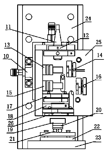
[0065] Embodiment 1: The schematic diagram of the micro-device of the present invention is as image 3 As shown, adjust the two-dimensional fiber pigtail fixing device so that the laser output from the fiber enters the non-polarizing beam splitter (NPBS), and use the NPBS fixing device to perform two-dimensional fine-tuning. The photoelectric receivers A and B are fixed by the two-dimensional fine-tuning device, which can cooperate with The NPBS fine-tuning device and the PBS fine-tuning device make the light beam completely incident on the photoelectric receivers A and B. The fixing device of the mirror can be moved up and down in one dimension and adjusted in angle, and its plane can be adjusted to be perpendicular to the optical axis. The plane of the fixed λ / 4 wave plate is also perpendicular to the optical axis. The fixing device of the measuring lens is adjusted to make three-dimensional micro-movement, and the angle can also be adjusted so that the beam passes through ...
Embodiment 2
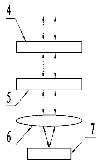
[0067] Embodiment 2: For the situation that needs simple and convenient device, can simplify this measuring device, remove λ / 4 waveplate, polarization beam splitter and photoelectric receiver B and its fixing device, this simple and convenient device still utilizes the principle of multi-beam interference, However, it is non-differential detection and only accepts one interference signal, which reduces the anti-interference ability and resolution, but it can still perform nanometer-level detection. After the incident linearly polarized light passes through the non-polarizing beam splitter, the polarization state remains unchanged, and the light intensity becomes half of the incident light intensity. Then the polarized light enters the mirror, part of it is reflected back to the original optical path, and part of it is transmitted into the interference cavity. The laser is reflected multiple times in the interference cavity, and the transmitted light is received by the photoelec...
Embodiment 3
[0068] Embodiment 3: the device of the present invention can be transformed according to the needs of actual use, and the figure 1 The DUT is replaced by a probe, the light spot is focused on the back of the probe cantilever beam, and the probe is used for contact measurement. Adjust the distance between the measuring head device system and the cantilever beam of the needle tip, focus the light spot on the top of the cantilever beam, and detect when the needle tip touches the sample. The needle tip fluctuates with the sample, causing the change of the length of the interference cavity. The device of the present invention can monitor the tiny fluctuation of the needle tip, so the device of the present invention can be used as a needle tip displacement sensor for stylus contact measurement, replacing the tunnel commonly used in contact measurement. Current effect and light lever method, etc.
PUM
 Abstract
Description
Claims
Application Information
 - R&D
- Intellectual Property
- Life Sciences
- Materials
- Tech Scout
- Unparalleled Data Quality
- Higher Quality Content
- 60% Fewer Hallucinations
Browse by: Latest US Patents, China's latest patents, Technical Efficacy Thesaurus, Application Domain, Technology Topic, Popular Technical Reports.
© 2025 PatSnap. All rights reserved.Legal|Privacy policy|Modern Slavery Act Transparency Statement|Sitemap|About US| Contact US: help@patsnap.com