
System for identifying the position of a three-dimensional machine in a fixed frame of reference

a three-dimensional machine and fixed frame technology, applied in the field of position identification system, can solve the problems of extreme heavyness and high cost, and achieve the effect of simple and low cos

Inactive Publication Date: 2003-08-26
HEXAGON TECH CENT GMBH
View PDF11 Cites 146 Cited by
  • Summary
  • Abstract
  • Description
  • Claims
  • Application Information

AI Technical Summary

Benefits of technology

Enables quick and accurate identification of machine position in three dimensions using a virtual slab, reducing costs and complexity by integrating bushings into the support surfaces, allowing for precise positioning without the need for extensive physical infrastructure.

Problems solved by technology

In this context, it is recalled that conventional slabs are constituted by massive plates having dimensions of 200 millimeters (mm).times.4000 mm.times.6000 mm, and they are extremely heavy and expensive.

Method used


Image

  • System for identifying the position of a three-dimensional machine in a fixed frame of reference
  • System for identifying the position of a three-dimensional machine in a fixed frame of reference
  • System for identifying the position of a three-dimensional machine in a fixed frame of reference

Examples


Embodiment Construction

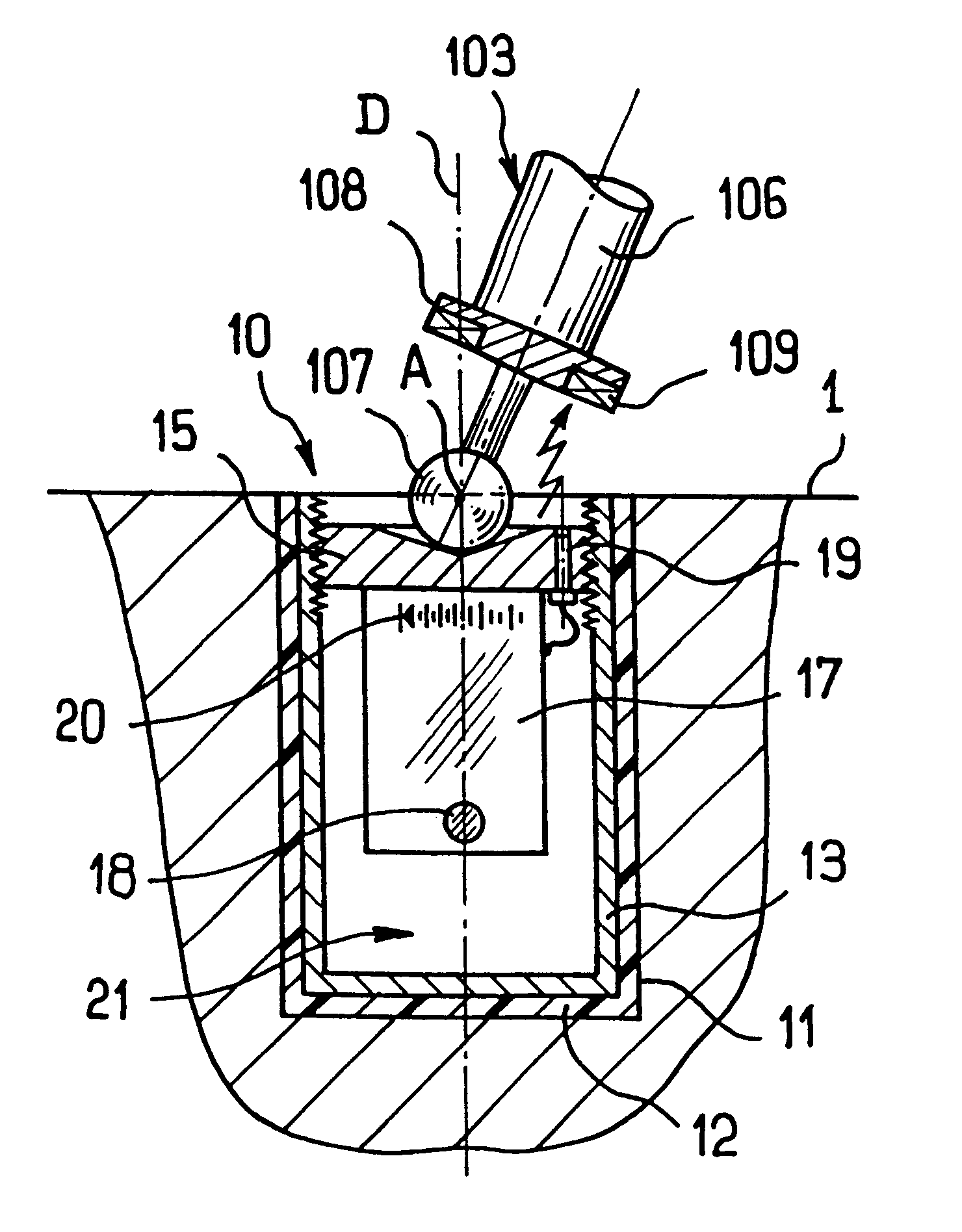
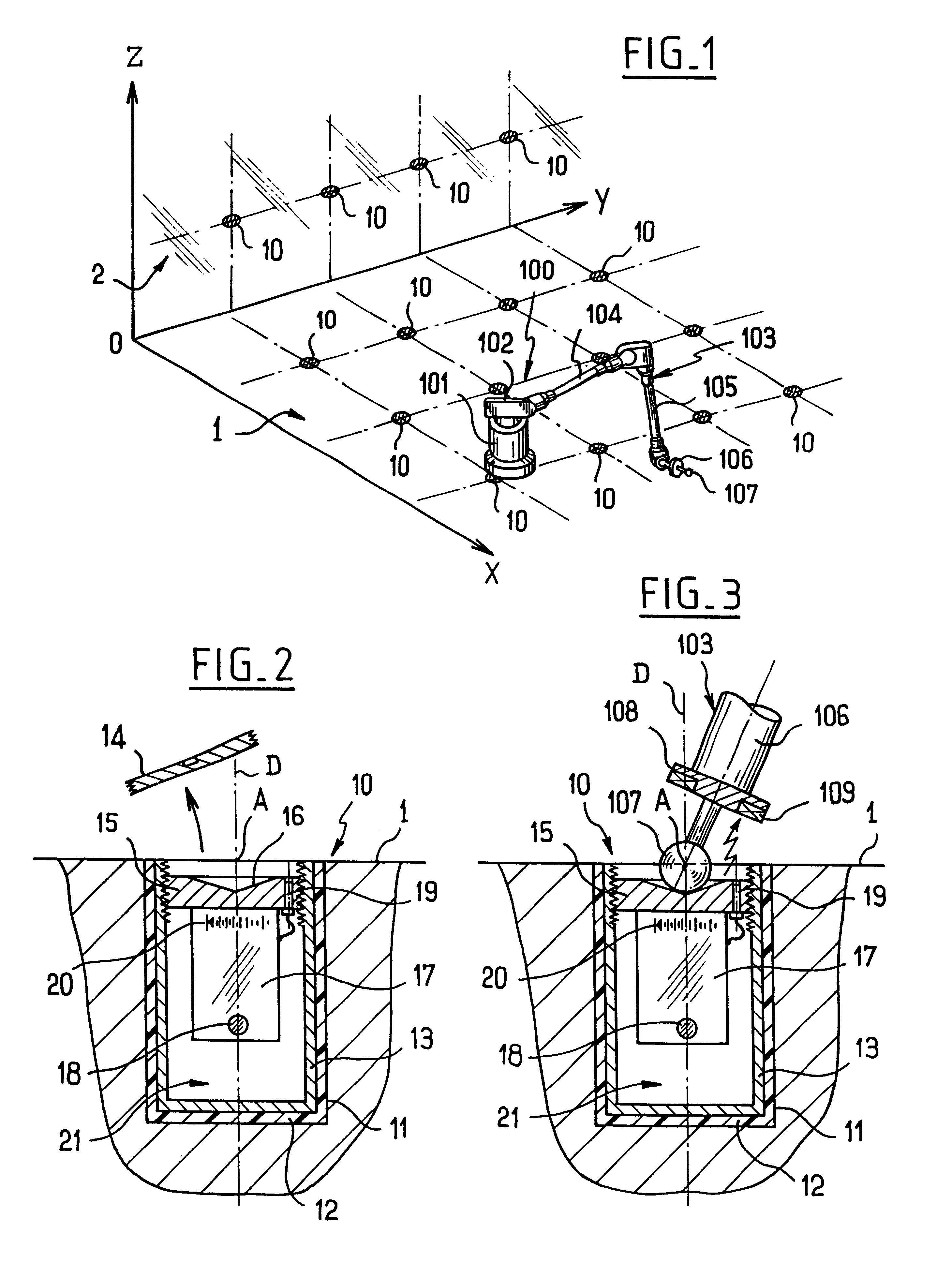
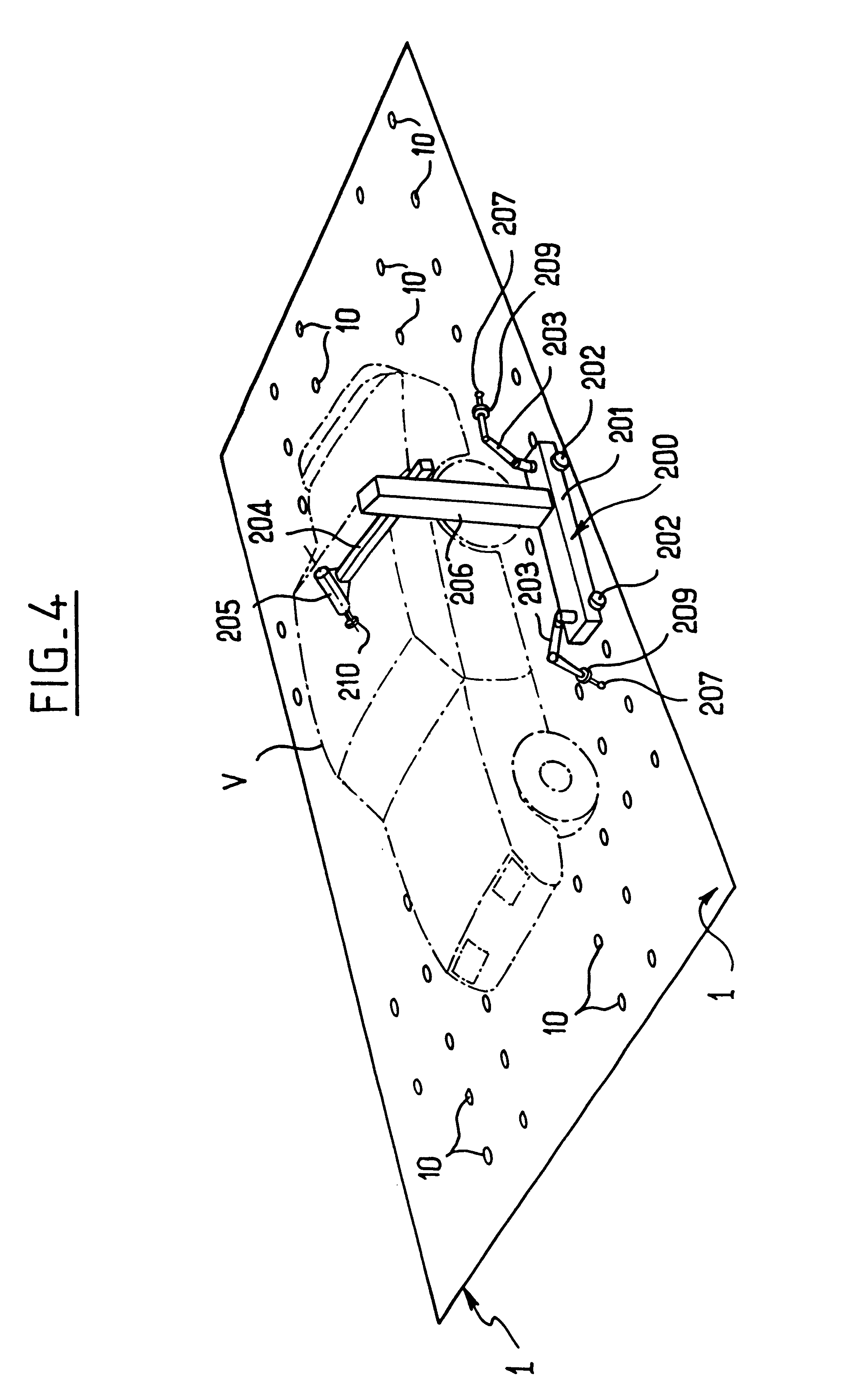
FIG. 1 shows a position-identifying system of the invention, in this case associated with a three-dimensional measuring machine 100, in a fixed frame of reference that is defined in three dimensions by three rectangular axes OX, OY, OZ. The three-dimensional machine 100 stands on an essentially plane support surface 1 which in this case is substantially horizontal. This surface is adjacent to another surface 2 which is essentially vertical.

In accordance with an essential characteristic of the invention, the support surface 1, and in this case also the vertical surface 2, are each fitted with a plurality of interactive integrated bushings 10, each bushing being fitted with emitter means for emitting a predetermined code that identifies the bushing concerned, thus making it possible to deduce the three-dimensional coordinates of a point associated with said support surface. An advantageous example of the structure for such an interactive integrated bushing is described below in greate...


PUM


Abstract

The present invention relates to a system for identifying the position of a machine in a fixed frame of reference, said machine standing on an essentially plane support surface. In the invention, the support surface is fitted with a plurality of interactive integrated bushings, each bushing being fitted with emitter means serving to emit a predetermined code enabling the bushing concerned to be identified and thus making it possible to deduce the coordinates of a point associated with said support surface, and the three-dimensional machine is fitted with at least one articulated arm terminating in a position sensor, said arm being fitted with receiver means capable of detecting the code emitted by a bushing amongst the plurality of bushings when the associated position sensor is brought into contact therewith.

Description

The present invention relates to a system for identifying the position of a three-dimensional machine in a fixed frame of reference.The three-dimensional machine concerned can equally well be a measuring machine or a machine for machining, e.g. a multi-spindle milling machine.In the particular field of motor vehicles, it can be necessary to identify the position of various points of the bodywork of a motor vehicle that has been involved in an accident or that is being assembled, so as to monitor its shape by identifying predetermined points of said bodywork by means of a three-dimensional measuring device associated with a reference structure, commonly referred to as a "slab". It is this operation of putting the vehicle on the slab that makes it possible to decide whether it can be put back on the road, possibly after repairing its deformed portions, or whether it should be scrapped.In this context, reference can be made to the following documents in the name of the Applicant: FR-A-...

Claims


Application Information

Patent Timeline
Patent Type & Authority Patents(United States)
IPC IPC(8): B25J9/16G01B21/02G01B21/04
CPCB25J9/1692G01B21/04G05B2219/37068G05B2219/39024G05B2219/39058
Inventor GRANGER, ROMAIN
Owner HEXAGON TECH CENT GMBH
Learn More