TWA measuring apparatus and TWA measuring method
A technology of measurement device and measurement method, which is applied in bioelectric signal measurement, diagnostic recording/measurement, medical science, etc.
- Summary
- Abstract
- Description
- Claims
- Application Information
AI Technical Summary
Problems solved by technology
Method used
Image

Examples
Embodiment 1)
[0050] Hereinafter, the TWA measuring device and the TWA measuring method of Embodiment 1 will be described. In this embodiment, the electrocardiogram waveform acquired by the measuring electrodes of the electrocardiogram is divided into two groups in increments of two beats, and the statistical difference of the measured values between the two groups is detected, thereby enabling TWA to be accurately measured .
[0051] (Structure of TWA measuring device)
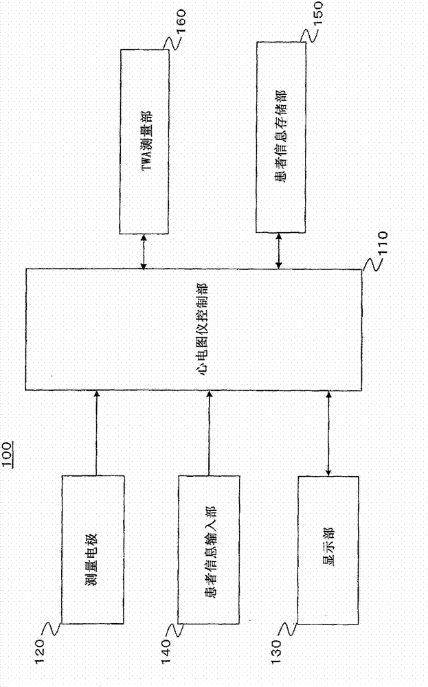
[0052] figure 1 is a block diagram of the TWA measuring device of the first embodiment. The TWA measuring device of Embodiment 1 was arranged in the electrocardiograph.
[0053] As shown in the figure, the TWA measurement device 100 includes an electrocardiograph control unit 110 , measurement electrodes 120 , a display unit 130 , a patient information input unit 140 , a patient information storage unit 150 , and a TWA measurement unit 160 .
[0054] The electrocardiograph control section 110 generally controls opera...
Embodiment 2)
[0146] Hereinafter, a TWA measuring device and a TWA measuring method of Embodiment 2 will be described. In this embodiment, the electrocardiogram waveform acquired by the measuring electrodes of the electrocardiograph is divided into two groups in increments of two beats, and into three groups in increments of three beats. Statistical differences between groups of measurements were then detected for each beat, and the presence of a mixture of significant statistical differences was checked to determine the presence of TWA.
[0147] (Structure of TWA measuring device)
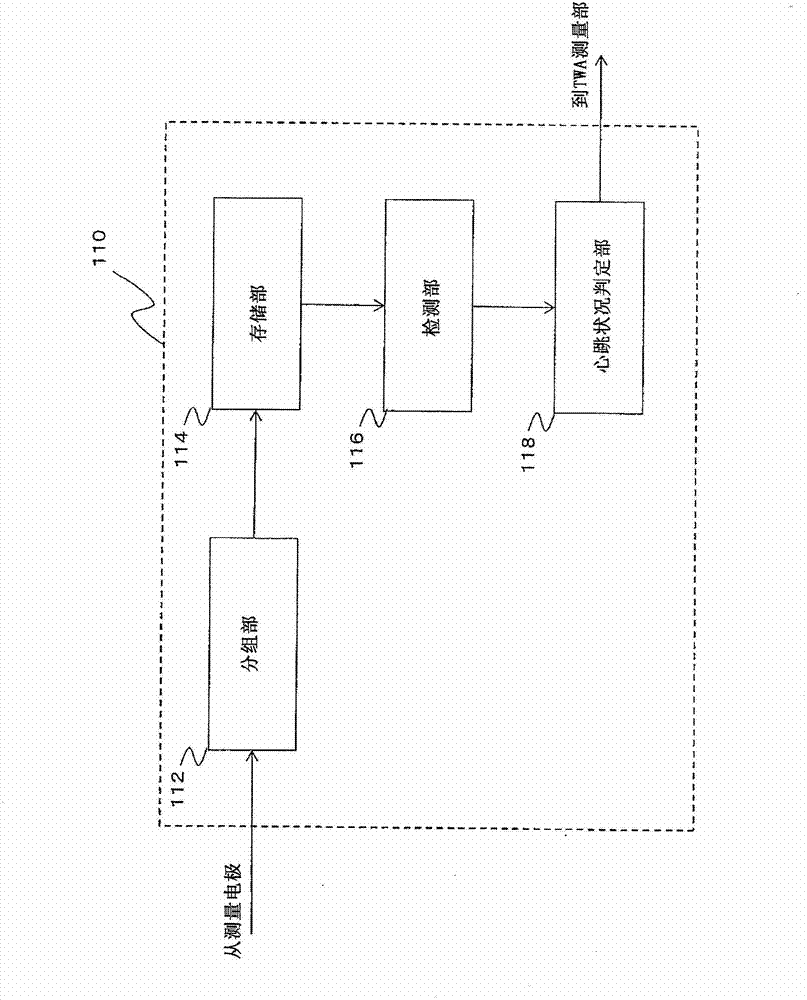
[0148] The structure of the TWA measurement device of Embodiment 2 and figure 1 with figure 2 The construction shown in is exactly the same. However, only the grouping section 112 , the detection section 116 , and the heartbeat condition determination section 118 of the electrocardiograph control section 110 are functionally different from those of Embodiment 1.
[0149] For each of a plurality of incremen...
Embodiment 3)
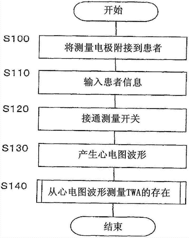
[0188] Hereinafter, a TWA measuring device and a TWA measuring method of Embodiment 3 will be described. In this embodiment, an electrocardiogram data input section is provided instead of the measurement electrodes 120 in Embodiment 1. The processes executed up to determining whether or not the presence of TWA is present based on the acquired electrocardiogram waveform are exactly the same as those of Embodiment 1. That is, execute with Figure 3 to Figure 6 The processing is exactly the same as that shown in the flowchart.
[0189] Although the TWA measuring device of Embodiment 1 is set in an electrocardiograph, the TWA measuring device of this embodiment is set in a computer instead of an electrocardiograph. This embodiment is used in cases where data is collected over a long period of time as in an electrocardiograph such as a Holter electrocardiograph or a monitoring electrocardiograph, and is downloaded to a computer for use in determining the presence or absence of TW...
PUM
 Abstract
Description
Claims
Application Information
 - R&D
- Intellectual Property
- Life Sciences
- Materials
- Tech Scout
- Unparalleled Data Quality
- Higher Quality Content
- 60% Fewer Hallucinations
Browse by: Latest US Patents, China's latest patents, Technical Efficacy Thesaurus, Application Domain, Technology Topic, Popular Technical Reports.
© 2025 PatSnap. All rights reserved.Legal|Privacy policy|Modern Slavery Act Transparency Statement|Sitemap|About US| Contact US: help@patsnap.com