
In-situ indentation mechanical testing device based on tensile compression and fatigue combined load mode

A composite load and testing device technology, which is applied in the direction of testing material strength by applying repetitive force/pulsation force, testing material strength by applying stable tension/compression, testing material hardness, etc. Performance testing, single load and other issues, to achieve the effect of compact structure, low cost and high precision

Active Publication Date: 2013-10-16
JILIN UNIV
View PDF5 Cites 21 Cited by
  • Summary
  • Abstract
  • Description
  • Claims
  • Application Information

AI Technical Summary

Problems solved by technology

[0003] At present, the development of related instruments for in-situ nanomechanical testing technology is still immature and still in its infancy. The specific performance is as follows: 1. The existing in-situ nanomechanical testing equipment has a single load and cannot correlate materials under composite loads. Mechanical performance test, so that it cannot simulate the actual condition of the workpiece in the real service state
2. The existing in-situ indentation material testing machine only conducts indentation tests under the free stress state of the workpiece, but rarely involves the phenomenon of the workpiece under the residual prestress

Method used


Image

  • In-situ indentation mechanical testing device based on tensile compression and fatigue combined load mode
  • In-situ indentation mechanical testing device based on tensile compression and fatigue combined load mode
  • In-situ indentation mechanical testing device based on tensile compression and fatigue combined load mode

Examples


Embodiment Construction

[0024] The detailed content of the present invention and its specific implementation will be further described below in conjunction with the accompanying drawings.

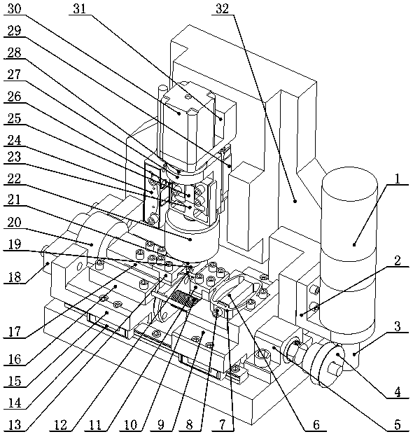
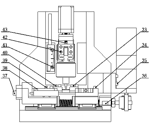
[0025] see Figure 1 to Figure 5 As shown, the in-situ indentation mechanical testing device based on tension-compression and fatigue composite load mode of the present invention includes a precision drive unit, tension-compression, fatigue composite load unit, indentation load unit, and precision sensing detection unit. The precision drive unit is composed of a DC servo motor 1, a worm 3 and a worm gear 4. The DC servo motor 1 is supported by a motor base 2, and the motor base 2 is fixed on one side of the base 32 by screws III 35, and its output shaft is fixedly connected with the worm 3. Drive the worm gear 4 to rotate, and drive with a large reduction ratio, which can realize quasi-static loading;

[0026] The tension-compression and fatigue composite load unit includes a tension-compression load module and a...


PUM


Abstract

The invention relates to an in-situ indentation mechanical testing device based on tensile compression and fatigue combined load mode, and belongs to the field of precise testing instruments. The device is mainly composed of a precise driving unit, a tensile compression and fatigue combined load unit, an indentation load unit, a precise sensing and detecting unit, wherein the precise driving unit can realize quasi-static load; the tensile compression and fatigue combined load unit enables the center of a testing piece to be kept unchanged basically; with combination of a high-resolution imaging system, observation of in-situ mechanical performances of a material can be carried out. A fatigue module is loaded on a tensile compression module, so that fatigue performance of the material can be tested by adopting the precise piezoelectric driving technology. The indentation load unit is arranged right above the testing piece and is pressed in the testing piece vertically, a lead screw stepping motor drives an indentation flexible hinge to feed linearly, and an indentation piezoelectric stack pressed in the testing piece drives precise indentation, so that cross-scale in-situ indentation mechanical test can be carried out. The device has the advantages of compact structure, small size, rapid response, high precision, low cost and the like.

Description

technical field [0001] The invention relates to the field of in-situ nanomechanical performance testing, in particular to the field of precision testing instruments, especially to an in-situ indentation mechanical testing device based on tension-compression and fatigue composite load modes, which can be used in different tension / compression and fatigue composite load modes. In-situ indentation tests of material samples under load prestressing. Background technique [0002] In-situ nanomechanical testing technology refers to testing the mechanical properties of materials at the nanometer scale, and using electron microscopes, atomic force microscopes, optical microscopes and other imaging instruments to analyze the response microscopic deformation, damage and even failure of materials under load. A mechanical testing technique for dynamic monitoring throughout the entire process. In the field of in-situ nanomechanical performance testing, parameters such as hardness, ela...

Claims


Application Information

Patent Timeline
Patent Type & Authority Applications(China)
IPC IPC(8): G01N3/40G01N3/38G01N3/08
Inventor 赵宏伟邵明坤程虹丙杨倚寒李士兵刘宏达张霖佟达鲁帅张鹏
Owner JILIN UNIV
Learn More