Left wheel popup box type porous pull-down plug graphite water gap device of electromagnetic slag smelter
What is Al technical title?
Al technical title is built by PatSnap Al team. It summarizes the technical point description of the patent document.
A graphite and slag technology, used in furnaces, furnace components, charge control, etc., can solve problems such as poor fluidity, inability to control high-temperature slag flow, blockage of channels, etc., achieving obvious cost advantages, superior conditioning performance, and waste slag. small effect
Active Publication Date: 2015-01-21
朱兴发
View PDF11 Cites 0 Cited by
Summary
Abstract
Description
Claims
Application Information
AI Technical Summary
This helps you quickly interpret patents by identifying the three key elements:
Problems solved by technology
Method used
Benefits of technology
Problems solved by technology
[0016] The controllable and constant flow of slag flow is the key to the production of high-quality mineral wool by the subordinate injection method and centrifugal method. The bottom of the holding furnace is thick, and there is a long section of nozzle temperature that is low. The molten slag will block the channel, and the high temperature cannot be controlled. flow rate of slag flow
[0017] The high-temperature slag will become mushy when the temperature drops to about 1300 degrees Celsius, and its fluidity is extremely poor
Method used
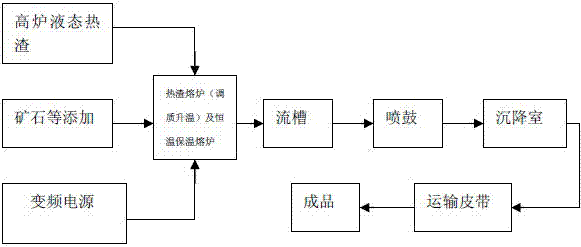
Image
Click on the blue label to locate the original text in one second.
Reading with bidirectional positioning of images and text.
Examples
Embodiment Construction
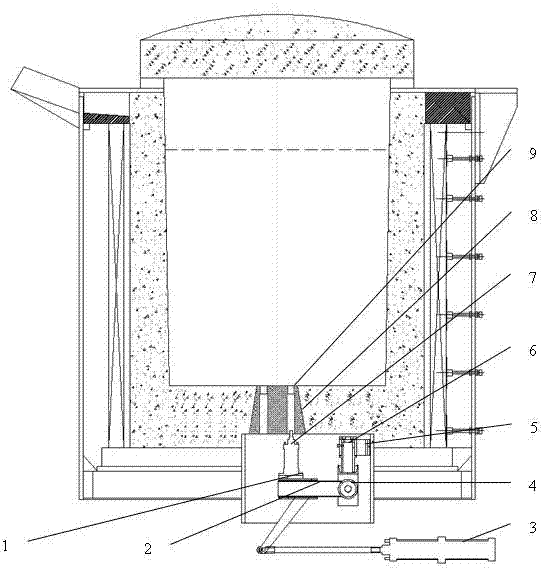
[0029] Control attached image 3 , 4 , Electromagnetic induction slag melting furnace left wheel cartridge type porous pull down plug graphite nozzle device, its structure includes moving arm 1, plug arm 2, plug cylinder 3, pin shaft 4, fixed frame 5, rotary shaft 6, top plug cylinder 7 and graphite nozzle 8, graphite plug 9; wherein graphite nozzle 8 is fixed in the furnace bottom lining, graphite plug 9 is inserted into graphite nozzle 8, top plug cylinder 7 is connected with graphite plug 9, top plug cylinder 7 Then it is fixed on the moving arm 1, and the moving arm 1 is set on the plug arm 2, which can move back and forth. The rotating shaft 6 is fixed on the fixed frame 5 and can rotate in the horizontal plane.
[0030] Working process: After the molten slag in the furnace reaches the water outlet requirement, the top plug cylinder 7 is extended to break the jelly at the bottom of the slag → the plug cylinder 3 is retracted, driving the plug arm 2, the moving arm 1 and...
PUM
Abstract
The invention provides a left wheel popup box type porous pull-down plug graphite water gap device of an electromagnetic slag smelter. The left wheel popup box type porous pull-down plug graphite water gap device of the electromagnetic slag smelter structurally comprises a moving arm, a plug shifting arm, a plug shifting air cylinder, a pin shaft, a fixed frame, a rotating shaft, a plug pushing air cylinder, a graphite water gap, a graphite plug and a porous cone. The left wheel popup box type porous pull-down plug graphite water gap device of the electromagnetic slag smelter has the advantages of achieving the effects that the blocking of high temperature slag in base flow of an electromagnetic induction slag smelter is relieved when the flow is open, and the flow is controlled at a constant temperature. Besides, the technological requirements of rock wool production are met, and a bottleneck is broken for the production of high quality rock wool. The designed bottom leakage deslagging water gap ensures flow accuracy, can be opened and closed at will, and does not waste melts. The energy consumption is low, thermal efficiency is high, the amount of waste residue is small, the fiber forming rate is high, and the cost advantage is obvious. The electromagnetic slag smelter is not only excellent in temperature rise and regulation performance, heat preservation performance and hardening and tempering performance, but also high in storage capacity, thereby laying a good foundation for scale production. The left wheel popup box type porous pull-down plug graphite water gap device has the advantages of being controllable in high temperature liquid state slag flow, smooth, free of blocking, safe, reliable, convenient to use and efficient.
Description
technical field [0001] The invention provides an electromagnetic induction slag melting furnace revolver cartridge type porous drop plug graphite nozzle device, which belongs to the technical field of slag melting equipment. Background technique [0002] The process energy consumption of blast furnace ironmaking accounts for about 60% of the total energy consumption of the iron and steel industry. Blast furnace slag is a kind of solid waste discharged from blast furnace ironmaking. Its treatment process not only consumes a lot of energy, but also discharges a lot of harmful substances. Therefore, it is necessary to carry out research on the recycling of blast furnace slag, which is an industrial solid waste. The slag discharged during the blast furnace ironmaking process, also known as blast furnace slag, can be divided into steelmaking pig iron slag, foundry pig iron slag, ferromanganese slag, etc. In some areas of China and the Soviet Union, titanium-magnetite is used fo...
Claims
Application Information
Patent Timeline
Application Date:The date an application was filed.
Publication Date:The date a patent or application was officially published.
First Publication Date:The earliest publication date of a patent with the same application number.
Issue Date:Publication date of the patent grant document.
PCT Entry Date:The Entry date of PCT National Phase.
Estimated Expiry Date:The statutory expiry date of a patent right according to the Patent Law, and it is the longest term of protection that the patent right can achieve without the termination of the patent right due to other reasons(Term extension factor has been taken into account ).
Invalid Date:Actual expiry date is based on effective date or publication date of legal transaction data of invalid patent.