
Control device and method for vacuum circuit breaker permanent magnetic mechanism based on double signal tracking

A technology of vacuum circuit breaker and permanent magnet mechanism, which is applied in the direction of computer control, program control, general control system, etc. It can solve the problems that the error must be within ±1ms, the inrush current and overvoltage suppression ability are low, and the contact bouncing can be weakened , Improve robustness and control accuracy, and avoid coil burnout

Active Publication Date: 2013-10-02
SHENYANG POLYTECHNIC UNIV
View PDF5 Cites 22 Cited by
  • Summary
  • Abstract
  • Description
  • Claims
  • Application Information

AI Technical Summary

Problems solved by technology

The current traditional action time compensation method is that the control system detects various influencing factors online and calculates the value of the action time change caused by them to determine the moment when the action signal is issued. This method can only adjust the opening and closing time The error is controlled at ±2ms, and the opening and closing phase error reaches ±36°. However, the premise of the practical application of synchronous closing and closing control technology in the smart grid is that the closing time error must be within ±1ms, so that it is possible to accurately Control the closing phase, so the current control system has a low ability to suppress inrush current and overvoltage in actual operation

Method used


Image

  • Control device and method for vacuum circuit breaker permanent magnetic mechanism based on double signal tracking
  • Control device and method for vacuum circuit breaker permanent magnetic mechanism based on double signal tracking
  • Control device and method for vacuum circuit breaker permanent magnetic mechanism based on double signal tracking

Examples


Embodiment Construction

[0042] An embodiment of the present invention will be further described below in conjunction with the drawings.

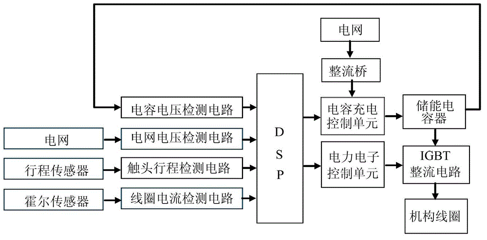
[0043] Such as figure 1 As shown, a vacuum circuit breaker permanent magnet mechanism control device based on dual-signal tracking includes a stroke sensor, a Hall sensor, a contact stroke detection circuit, a DSP processor, a rectifier bridge, an energy storage capacitor and an IGBT rectifier circuit, and also includes Capacitor voltage detection circuit, grid voltage detection circuit, coil current detection circuit, capacitor charging control unit and power electronic control unit;

[0044] In the embodiment of the present invention, the DSP processor adopts the TMS320F28335 model (such as figure 2 As shown in (a) and (b)), the stroke sensor adopts SGC6T200 grating sensor, and its output terminal YC-18-7 (as shown in Table 1) A (plug No. 3), B (plug No. 4) , C (plug No. 6) is connected to the input terminals A1, A2, A3 of the contact stroke detection circuit in turn...


PUM


Abstract

The invention provides a control device and method for a vacuum circuit breaker permanent magnetic mechanism based on the double signal tracking, and belongs to the field of the automatic control of electrical equipment. According to the invention, a double closed-loop PID control algorithm is adopted to enable a vacuum circuit breaker permanent magnetic operating mechanism contact terminal with movement characteristics to be in a controlled state, so as to improve the robustness and control precision of a control system; field coil electric current of a current sensor measurement mechanism in the control device is utilized to enable the field coil electric current to be subjected to whole-course control, so as to avoid the possibility of coil burning down; a contact terminal journey dynamic curve is selected to reduce the impulsive force of a moving contact reaching an extreme position, so as to improve the reliability of the mechanism action and prolong the service life of the mechanism; the divide-shut brake voltage is improved, and the contact terminal journey curve is selected to reduce energy loss of the contact terminal caused by collision, so as to achieve the energy-saving effect, enable the circuit breaker to complete brake reclosing operation for more times under the same application condition, effectively prolong the service life of the circuit breaker, and improve the stability of an electric power system simultaneously.

Description

Technical field [0001] The invention belongs to the field of electrical appliance automation control, and in particular relates to a vacuum circuit breaker permanent magnet mechanism control device and method based on dual-signal tracking. Background technique [0002] The operating phase of the traditional switch is random, and it is easy to generate a large inrush current and a high induced overvoltage when the power system is switched on and off, which leads to a reduction in the service life of the switch device and the power supply quality of the power system. Therefore, studying the intelligent control technology of the circuit breaker can not only ensure the reliability, stability and improve the power quality of the power supply, but also have important meanings to effectively improve the production efficiency of the enterprise and the service life of the equipment. [0003] In principle, the synchronous closing and closing control technology can effectively weaken the inru...

Claims


Application Information

Patent Timeline
IPC IPC(8): G05B19/042
Inventor 徐建源汤庚林莘史可鉴
Owner SHENYANG POLYTECHNIC UNIV
Learn More