A dynamic balancing method for an ultra-precise direct-drive hydrostatic spindle
A hydrostatic spindle, direct-drive technology, used in static/dynamic balance testing, measuring devices, instruments, etc., can solve the problem of inability to achieve precise dynamic balance of ultra-precision hydrostatic spindle rotors, and achieve accurate dynamic balance results. Reliable, balanced precision, effect of eliminating influence
- Summary
- Abstract
- Description
- Claims
- Application Information
AI Technical Summary
Problems solved by technology
Method used
Image
Examples
specific Embodiment approach 1
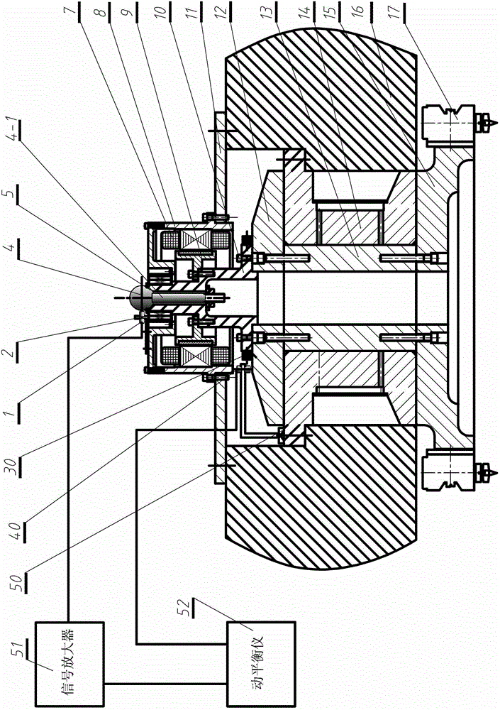
[0010] Specific implementation mode one: combine figure 1 Describe this embodiment, the online testing method described in this embodiment is based on including a vertical ultra-precision direct-drive hydrostatic spindle system, a measurement system, and a dynamic balancer 52;
[0011] The vertical ultra-precision direct-drive hydrostatic spindle system includes a servo motor, an ultra-precision direct-drive hydrostatic spindle (rotating part, namely the rotor part), a machine tool beam support plate (machine tool beam cover plate) 11, a spindle bushing 14 (stator Part), machine tool beam 16 and micro-feed tool rest 17; ultra-precision direct-drive hydrostatic spindle rotor consists of input end part 10, upper thrust plate 12, shaft center 13, bottom stop The push plate 15 is fixedly connected; the servo motor includes a motor stator 7, a motor rotor 9 and a casing 8; the dynamic balance source signal measurement system consists of a measurement reference ball 4 installed at t...
specific Embodiment approach 2
[0014] Specific implementation mode two: combination figure 1 To illustrate this embodiment, the specific implementation process of the dynamic balancing method is as follows: Step 1, install the measurement reference: install the standard ball 4 on the upper end of the detection rod 4-1 on the input end part 10 of the ultra-precision direct-drive static pressure spindle In the tapered installation datum plane 5 processed on the end face, the lower end of the detection rod 4-1 is fixed inside the hollow input end part 10 through a nut; Step 2, install the high-precision displacement sensor 1 and the photoelectric speedometer 40: first, place the high-precision displacement sensor The sensor bracket 2 is fixed on the casing of the motor stator, and then the high-precision displacement sensor 1 is installed through the mounting hole on the bracket 2, and the photoelectric speedometer 40 is installed on the speedometer bracket 50 at the same time, and the speedometer bracket 50 is...
specific Embodiment approach 3
[0016] Specific implementation mode three: combination figure 1 To illustrate this embodiment, the standard ball of this embodiment is ground and polished, and the material is special stainless steel. After polishing, the PV value of the surface shape accuracy is better than λ / 20 (wherein λ=0.633 μm), and the surface roughness is better than 2nm. Other compositions and connections are the same as those in Embodiment 1 or Embodiment 2.
PUM
 Abstract
Description
Claims
Application Information
 - R&D
- Intellectual Property
- Life Sciences
- Materials
- Tech Scout
- Unparalleled Data Quality
- Higher Quality Content
- 60% Fewer Hallucinations
Browse by: Latest US Patents, China's latest patents, Technical Efficacy Thesaurus, Application Domain, Technology Topic, Popular Technical Reports.
© 2025 PatSnap. All rights reserved.Legal|Privacy policy|Modern Slavery Act Transparency Statement|Sitemap|About US| Contact US: help@patsnap.com

