
Depth micrometer verification special-purpose testing fixture and verification method

A technology of depth micrometer and inspection tool, which is applied in the direction of micrometer, mechanical depth measurement, angle/taper measurement, etc., and can solve problems such as high roughness requirements, low work efficiency, and easy-to-scratch platforms 4

Pending Publication Date: 2020-11-24
FACTORY 5721 OF PLA
View PDF0 Cites 0 Cited by
  • Summary
  • Abstract
  • Description
  • Claims
  • Application Information

AI Technical Summary

Problems solved by technology

[0003] In the national standard verification regulations, the standard steel ball detection method is used to detect the parallelism between the measuring surface of the measuring rod and the measuring surface of the bottom plate. By changing the position of the steel ball 3, different positions of the measuring surface of the measuring rod 1-1 in the depth micrometer 1 Contact the standard steel ball 3 to obtain a set of measurement data, compare the measurement data with the diameter of the standard steel ball 3, and obtain the parallelism deviation between the measurement surface of the depth micrometer measuring rod 1-1 and the measurement surface of the bottom plate 1-2, Since the steel ball 3 is directly placed on the platform 4 during the detection process, it is very easy to roll back and forth. Not only is the position of the steel ball 3 difficult to control, the work efficiency is low, and it is easy to scratch the platform 4 at the same time. 4. The surface roughness requirements are very high. After the platform 4 is scratched, the measurement standard will be inaccurate, resulting in poor accuracy of the test results.

Method used


Image

  • Depth micrometer verification special-purpose testing fixture and verification method
  • Depth micrometer verification special-purpose testing fixture and verification method
  • Depth micrometer verification special-purpose testing fixture and verification method

Examples


Embodiment Construction

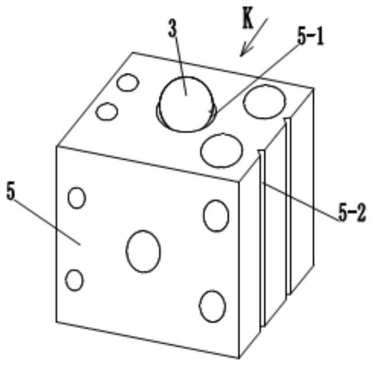
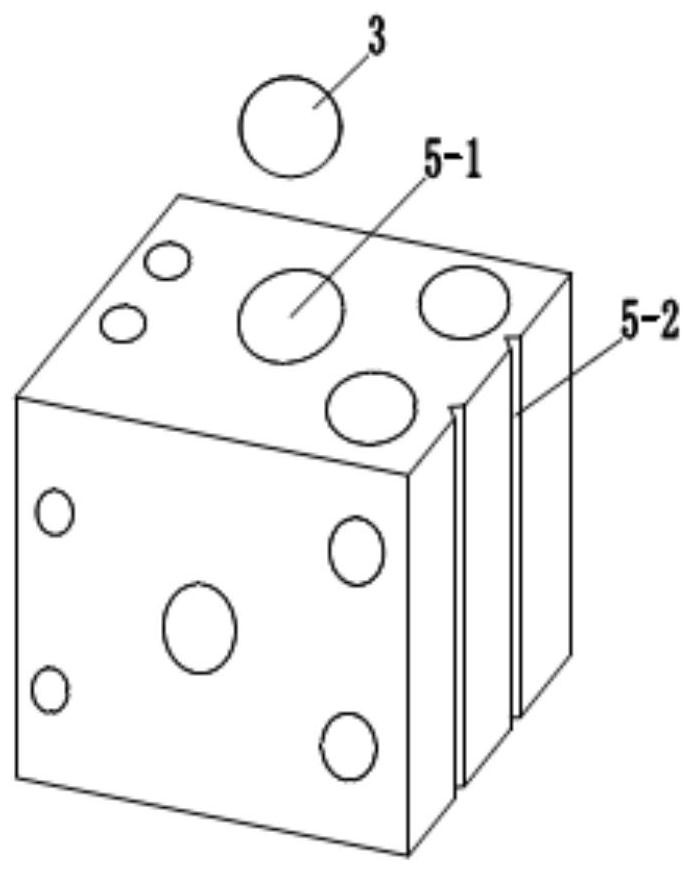
[0034] The invention provides a special inspection tool and inspection method for depth micrometer verification, especially a special inspection tool and inspection method for detecting the parallelism between the measurement surface of the measuring rod and the measurement surface of the bottom plate during the inspection process of the depth micrometer. The following is combined with the accompanying drawings And the specific embodiment will further illustrate the present invention.

[0035] See Figure 2, image 3 , Figure 4 , Figure 5 , the special inspection tool for depth micrometer verification according to the present invention includes a rectangular measuring block 5 and a standard steel ball 3; the rectangular measuring block 5 is provided with several groups of circular grooves 5-1 of different sizes and specifications on its outer surface, The bottom surface of the circular groove 5-1 is a spherical arc surface; the standard steel balls 3 are configured in sever...


PUM


Abstract

The invention relates to a depth micrometer verification special-purpose testing fixture and a verification method. The depth micrometer verification special-purpose testing fixture comprises a rectangular measuring block and a standard steel ball. The outer surface of the rectangular measuring block is provided with a plurality of groups of circular grooves with different sizes and specifications, and the bottom surfaces of the circular grooves are spherical cambered surfaces; a plurality of groups of standard steel balls are arranged, and the diameter sizes of the standard steel balls respectively correspond to the circular grooves with different sizes and specifications; and the roughness Ra of the outer surface of the rectangular measuring block, the bottom surface of the circular groove and the surface of the standard steel ball is less than 0.1 mm. According to the invention, through the design of the combined structure of the standard measuring block and the standard steel ball,the method for detecting the parallelism between the measuring surface of the bottom plate of the depth micrometer and the measuring surface of the measuring rod is innovated, and the purposes of ensuring the accuracy of a detection result and improving the working efficiency are achieved.

Description

technical field [0001] The invention relates to a checking tool and a verification method, in particular to a special checking tool and a verification method for detecting the parallelism between the measurement surface of a measuring rod and the measurement surface of a bottom plate during the verification process of a depth micrometer. Background technique [0002] as attached figure 1 As shown, the depth micrometer 1 is an instrument for measuring the distance between the measuring surface of the bottom plate and the measuring surface of the measuring rod by using the principle of a spiral pair, and consists of a micrometer cylinder 1-1, a fixed sleeve 1-2, a measuring rod 1-3, and a bottom plate 1-4 and locking device 1-5 and other components, mainly used for measuring the depth and steps of precision workpieces during machining. For the depth micrometer whose measurement surface of measuring rod 1-3 is plane, since the parallelism between the measuring surface of botto...

Claims


Application Information

Patent Timeline
IPC IPC(8): G01B5/24G01B3/18G01B5/18
CPCG01B3/18G01B5/18G01B5/24
Inventor 邵竑文高雷孟亮张大鹏
Owner FACTORY 5721 OF PLA
Learn More