
A clamping device and a clamping method

A technology of clamping and clamping holes, which is used in positioning devices, clamping, manufacturing tools, etc., can solve the problems of low efficiency of clamping devices and uneven force on the workpiece, and achieve the effect of convenient clamping or disassembly and assembly.

Active Publication Date: 2021-05-25
GUANGZHOU HAOZHI ELECTROMECHANICAL
View PDF0 Cites 0 Cited by
  • Summary
  • Abstract
  • Description
  • Claims
  • Application Information

AI Technical Summary

Problems solved by technology

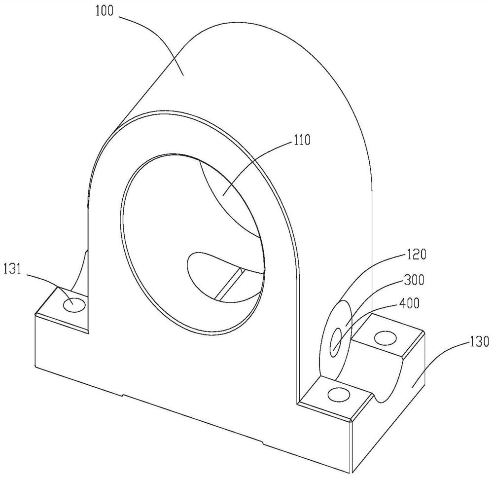
[0003] In order to overcome the deficiencies of the prior art, one of the objectives of the present invention is to provide a clamping device and a clamping method, which can solve the problems of low efficiency of the existing clamping device and uneven force on each part of the workpiece

Method used


Image

  • A clamping device and a clamping method
  • A clamping device and a clamping method

Examples


Embodiment Construction

[0024] Below, the present invention will be further described in conjunction with the accompanying drawings and specific implementation methods. It should be noted that, under the premise of not conflicting, the various embodiments described below or the technical features can be combined arbitrarily to form new embodiments. .

[0025] It should be noted that when a component is said to be "fixed" to another component, it can be directly on the other component or there can also be an intervening component. When a component is said to be "connected" to another component, it may be directly connected to the other component or there may be intervening components at the same time. When a component is said to be "set on" another component, it may be set directly on the other component or there may be an intervening component at the same time. The terms "vertical," "horizontal," "left," "right," and similar expressions are used herein for purposes of illustration only.

[0026] Un...


PUM


Abstract

The invention discloses a clamping device, which comprises a clamping main body. The clamping main body is provided with a clamping hole, and a workpiece that needs to be clamped is located in the clamping hole. It also includes a first slider, a second slider, and a connecting piece. The main body of the holding clamp is provided with a sliding hole, and when the connecting piece moves, the first slider and the second slider are simultaneously driven to approach in the sliding hole, so as to hold the workpiece tightly. In the present invention, through the design of the first slider and the second slider with opposite threads, the movement of the stud can make the first slider and the second slider move toward each other or move backwards at the same time, making it more convenient to hold or disassemble; The design of the arc surface makes the clamping device self-centering. The invention also discloses a clamping method.

Description

technical field [0001] The invention relates to the field of clamping technology, in particular to a clamping device and a clamping method. Background technique [0002] The main shaft clamping structure on the existing market is mostly slotted type, which is locked by screws and loosened by the top of the screw. When clamping tightly, the deformation of the clamping will make the inner hole squeeze the main shaft body, the force on each part of the main shaft is uneven, and the central axis of the main shaft It is also prone to offset, and even needs to be re-adjusted, which affects the processing efficiency; and when this type of clamp is disassembled, it is necessary to tighten and loosen the screws many times, which makes the processing preparation time too long and affects the processing efficiency. Contents of the invention [0003] In order to overcome the deficiencies of the prior art, one of the objectives of the present invention is to provide a clamping device a...

Claims


Application Information

Patent Timeline
Patent Type & Authority Patents(China)
IPC IPC(8): B23Q3/12
CPCB23Q3/12
Inventor 何建华汤秀清
Owner GUANGZHOU HAOZHI ELECTROMECHANICAL
Learn More