Pulling machine unloading manipulator system
What is Al technical title?
Al technical title is built by PatSnap Al team. It summarizes the technical point description of the patent document.
A technology of manipulators and upper waist seats, applied in manipulators, program-controlled manipulators, metal processing, etc., can solve the problems of low production efficiency and high labor intensity, and achieve the effects of increased efficiency, fast and accurate transposition, and avoiding hydraulic shock
Inactive Publication Date: 2015-09-30
ZHEJIANG INT STUDIES UNIV
View PDF5 Cites 0 Cited by
Summary
Abstract
Description
Claims
Application Information
AI Technical Summary
This helps you quickly interpret patents by identifying the three key elements:
Problems solved by technology
Method used
Benefits of technology
Problems solved by technology
[0002] The broaching machine is a machine tool that uses a broach to process the material to form the material into the desired shape. In many domestic factories, the loading and unloading of the workpiece on the broaching machine is still done manually, which has high labor intensity and low production efficiency.
Method used
Image
Click on the blue label to locate the original text in one second.
Reading with bidirectional positioning of images and text.
Examples
Embodiment Construction
[0024] The technical solutions of the present invention will be described in further detail below with reference to the accompanying drawings and embodiments.
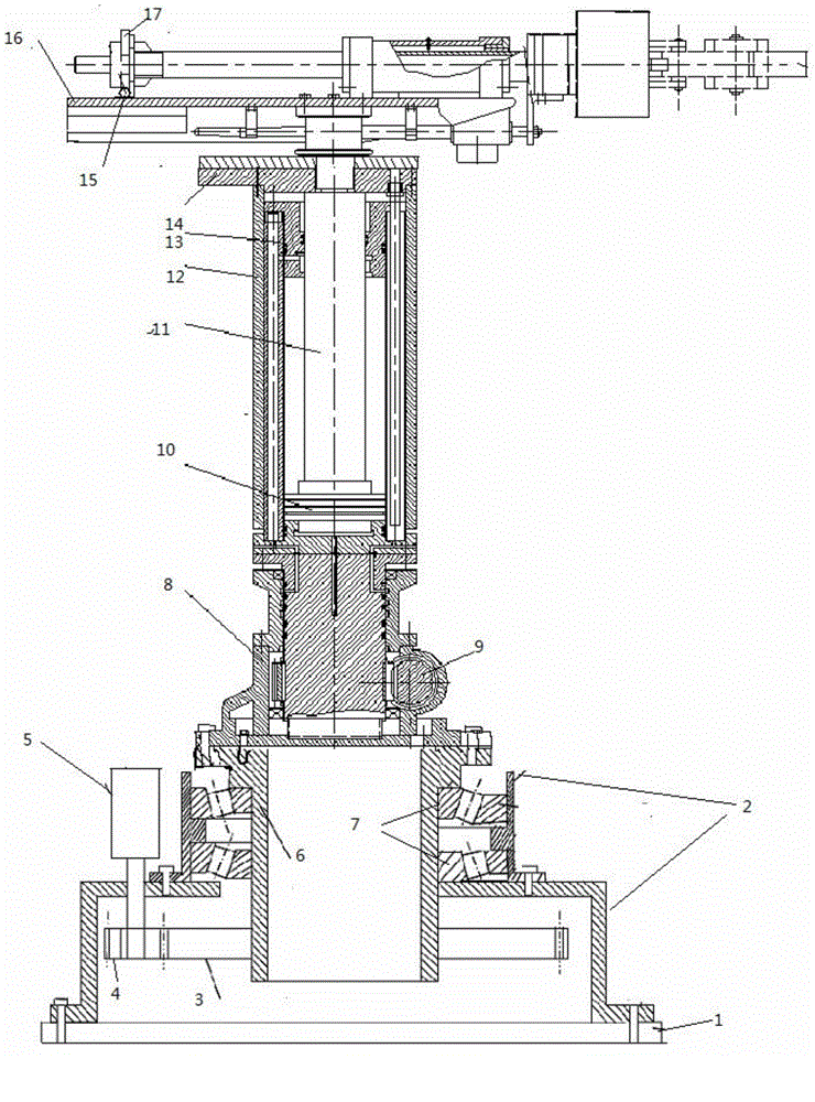
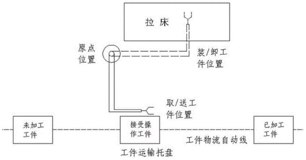
[0025] Such as figure 1 , figure 2 , Figure 4 As shown, a broaching machine loading and unloading manipulator system, the object of the present invention is to provide a broaching machine loading and unloading manipulator system for the deficiencies of the prior art.
[0026] The present invention includes an executive mechanism, a driving mechanism and a hydraulic control mechanism, and the driving mechanism includes a waist seat 2, a large gear 3, a pinion 4, a stepping motor 5, a waist rotary shaft 6, a tapered roller bearing 7, a fixed column 8, and a rack Cylinder 9;
[0027] The waist seat 2 includes an upper waist seat and a lower waist seat. The upper waist seat is a cylindrical shape with open ends, and an annular protrusion is provided on the inner surface. Two tapered roller bearings 7 are arranged in t...
PUM
Abstract
The invention discloses a loading and unloading manipulator system of a broaching machine, which comprises an executing mechanism, a driving mechanism and a hydraulic control mechanism, wherein the driving mechanism comprises a waist seat, a bull gear, a pinion, a stepping motor, a waist revolving shaft, tapered roller bearings, a fixed upright and a rack cylinder; the executing mechanism comprises a rising oil cylinder, a rising oil cylinder piston, a rising oil cylinder piston rod, a rising guide rod, a sleeve, a lifting platform, a rolling bearing, a support plate, a support frame, a translation oil cylinder, a translation oil cylinder piston rod, a guide rod, a guide bushing, an annular sleeve and a manipulator; the manipulator comprises a paw and a telescopic oil cylinder; and the hydraulic control mechanism comprises a three-phase alternating current asynchronous motor, a hydraulic pump, an oil filter, an oil tank, a two-position two-way solenoid directional valve, a one-way valve, a pilot overflow valve, a three-position four-way solenoid directional valve, a speed regulating valve and a hydraulic cylinder. The system can guarantee the positioning control precision, and reduces impact and vibration to the greatest extent, so that the safety of the system is guaranteed.
Description
technical field [0001] The invention belongs to the application field of industrial robots, and relates to a loading and unloading manipulator system for broaching machines. Background technique [0002] Broaching machine is a machine tool that processes materials with a broach to form the material into the desired shape. In many domestic factories, the loading and unloading of workpieces on broaching machines is still done manually, which is labor-intensive and low in production efficiency. In order to improve the efficiency of production and processing, reduce costs, and develop the production line into a flexible manufacturing system to adapt to modern automated large-scale production, it is urgent to design a broaching machine loading and unloading manipulator for specific production processes and use robot technology to replace manual labor. Work, a fully automatic high-tech product that replaces traditional manual loading and unloading. Contents of the invention [...
Claims
Application Information
Patent Timeline
Application Date:The date an application was filed.
Publication Date:The date a patent or application was officially published.
First Publication Date:The earliest publication date of a patent with the same application number.
Issue Date:Publication date of the patent grant document.
PCT Entry Date:The Entry date of PCT National Phase.
Estimated Expiry Date:The statutory expiry date of a patent right according to the Patent Law, and it is the longest term of protection that the patent right can achieve without the termination of the patent right due to other reasons(Term extension factor has been taken into account ).
Invalid Date:Actual expiry date is based on effective date or publication date of legal transaction data of invalid patent.