
Capacitive high-voltage equipment insulation aging diagnostic test system and working method thereof

A technology for capacitive high-voltage equipment and diagnostic tests, which is applied in the direction of testing dielectric strength, measuring devices, and instruments, and can solve problems such as low test efficiency, large test device volume, and shortened life of high-voltage equipment

Active Publication Date: 2013-09-25
GAUSS ELECTRONICS TECH
View PDF5 Cites 38 Cited by
  • Summary
  • Abstract
  • Description
  • Claims
  • Application Information

AI Technical Summary

Problems solved by technology

This high-voltage test method mainly has the following defects: (1) Since the test voltage is as high as tens of thousands of volts or even millions of volts, the volume of the test device is large, and the test requires huge manpower and material resources, which also makes the test efficiency not high. There is still insulation damage to the tested high-voltage equipment
(2) The over-high voltage test is mainly carried out in the standard test base. At the same time, there are many environmental and personal safety factors that need to be considered in the high-voltage equipment test operation site. Therefore, high-voltage tests are generally arranged in a targeted manner, and it is impossible to conduct high-voltage tests The equipment undergoes frequent high-voltage tests, and frequent withstand voltage tests on large areas will also lead to shortened life of high-voltage equipment or insulation damage

Method used


Image

  • Capacitive high-voltage equipment insulation aging diagnostic test system and working method thereof
  • Capacitive high-voltage equipment insulation aging diagnostic test system and working method thereof
  • Capacitive high-voltage equipment insulation aging diagnostic test system and working method thereof

Examples


Embodiment 1

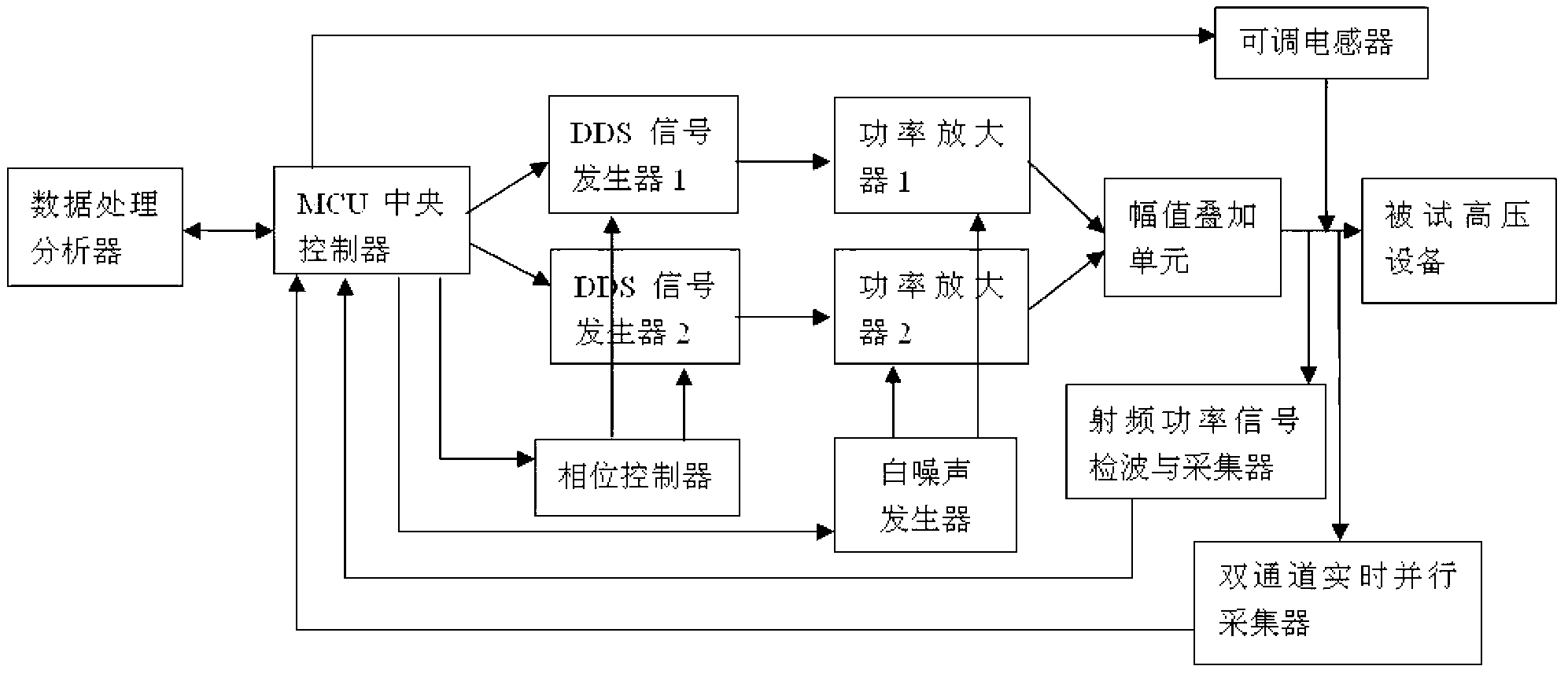
[0036] Such as figure 1 shown. For insulation aging diagnosis of transformers, the test equipment is a capacitive high-voltage equipment insulation aging diagnosis test system, including MCU central controller, DDS signal generator 1, DDS signal generator 2, phase controller, power amplifier 1, power amplifier 2. White noise generator, amplitude superposition unit, adjustable inductor, dual-channel real-time parallel collector, RF power signal detection and collector, and data processing analyzer. The MCU central controller is responsible for controlling two DDS signal generators, white noise generators, phase controllers, adjustable inductors and corresponding acquisition devices, and finally the acquired data is sent to the data processing analyzer for calculation and statistical analysis. The data processing analyzer can be a separate MCU processor, or a mobile PC, or an industrial computer, or a tablet computer, or other handheld mobile smart devices with data access and...

Embodiment 2

[0086] Such as figure 1 As shown, the same place as that of Embodiment 1 will not be repeated, the difference is that the impact superimposed insulation aging test is carried out for the cable. The tested cable is an XLPE insulated single-phase cable with a rating of 220kV and a length of 40 kilometers. The frequency of the reference test signal is 1000Hz, the amplitude is 2kV, the rising edge of the impact test signal is 1uS, the total pulse width is 20uS, the amplitude is 200V, the superposition phase is 90 degrees, and the adjustable inductance value is 0.

[0087] This test mode can not only test and analyze parameters such as impedance, phase, power, and STFT of the capacitive insulating layer, but also search and identify cable faults and defect locations through the time-domain pulse reflection method. The TDR proposed by the present invention is based on the shock superposition test environment, so the pulse signal obtained is different from the pulse signal of the t...

Embodiment 3

[0099] Such as figure 1 As shown, the same places as in Example 1 will not be repeated, the difference is that: the impact superimposed insulation aging test is carried out for the capacitive bushing. The capacity of the capacitive bushing is small, and the parameters obtained from the LRC energy storage response are relatively weak. You can choose not to analyze the LRC energy storage response. At the same time, because of its short length, it is the same as the transformer, and the capacitive bushing does not perform the TDR analysis function. . Other single-frequency shock superposition tests, shock superposition frequency sweep tests, and STFT test data and format are the same as those in Example 1.

[0100]

[0101] Table 16 Comprehensive analysis table of capacitive bushing aging based on impact superposition test

[0102] As shown in Table 16, the impedance of the single-frequency impact superposition test of the capacitive bushing is qualified, and it can be cons...


PUM


Abstract

The invention discloses a capacitive high-voltage equipment insulation aging diagnostic test system and a working method thereof. Double-frequency time-varying signals are used in the system for carrying out an overlaying impact test, two independent DDS signal generators, a power amplifier with white noise control, an amplitude overlaying unit and a controllable inductive load which is in output connection with the amplitude overlaying unit in series or in parallel form a composite aliasing waveform output loop, a set of information processing analysis method is combined, and insulation aging of tested high-voltage equipment is subjected to test diagnosis. Compared with the prior art, the insulation aging diagnosis test can be completed by exerting a test signal which is lower than a nominal voltage on the tested high-voltage equipment, insulation damage cannot be caused on the high-voltage equipment, the test can be carried out at any time, on-site testing is convenient, testing efficiency is high, compared with an existing diagnosis test signal which is single in waveform, the overlaying impact test signals can obtain abundant testing parameters, and potential fault of the high-voltage equipment can be easily found.

Description

technical field [0001] The invention relates to a high-voltage equipment insulation aging diagnostic test system, in particular to a capacitive high-voltage equipment insulation aging diagnostic test system capable of performing diagnostic tests without outputting the rated voltage of the high-voltage equipment and a working method thereof. Background technique [0002] Traditional high-voltage equipment insulation test methods, including power frequency test and impact test, usually apply a voltage of 1-3 times the rated voltage value to the high-voltage equipment under test, and then study the output current value or impedance value under this voltage. This high-voltage test method mainly has the following defects: (1) Since the test voltage is as high as tens of thousands of volts or even millions of volts, the volume of the test device is large, and the test requires huge manpower and material resources, which also makes the test efficiency not high. There is also insula...

Claims


Application Information

Patent Timeline
Patent Type & Authority Applications(China)
IPC IPC(8): G01R31/00G01R31/12
Inventor 张方荣张建梁建华杨堂华白彪史俊李文亮
Owner GAUSS ELECTRONICS TECH
Learn More