
Method for weakening corner part heat transmission of continuous casting crystallizer

A continuous casting crystallizer and crystallizer technology, which is applied in the field of weakened corner heat transfer of square, rectangular or plate continuous casting crystallizers, and can solve the problems of detachment of billet shells at the corners, difficulty in mold manufacturing and design, and high cost

Active Publication Date: 2013-09-25
BAOSHAN IRON & STEEL CO LTD
View PDF10 Cites 16 Cited by
  • Summary
  • Abstract
  • Description
  • Claims
  • Application Information

AI Technical Summary

Problems solved by technology

The two-dimensional cooling of the upper part of the crystallizer corner is higher than that of the lower part, and the production cost and design of such a crystallizer are difficult
[0005] In the prior art, there are still many similar continuous casting crystallizers involved in the above-mentioned patented technology. Some crystallizers have industrial application examples, and some have no application examples. The reason is that although the above crystallizers can improve crystallization to a certain extent The heat transfer at the corner of the crystallizer, but it also brings the difficulty of manufacturing and high cost of popularization; at the same time, the wall thickness of the upper corner of some crystallizers is thinner than that of the lower part, which instead causes the enhancement of corner cooling instead of weakening
In the prior art, it is also believed that the two-dimensional heat transfer at the corner of the crystallizer causes severe cooling at the corner, which will immediately cause the billet shell at the corner to separate from the mold wall. Because the thermal resistance of the air gap is too large, the cooling at the corner is weaker than that at the side. , the corner cooling should be enhanced, otherwise it will also cause defects such as non-uniform solidification cracks in the billet shell

Method used


Image

  • Method for weakening corner part heat transmission of continuous casting crystallizer
  • Method for weakening corner part heat transmission of continuous casting crystallizer
  • Method for weakening corner part heat transmission of continuous casting crystallizer

Examples


Embodiment 1

[0021] Example 1 as figure 1 As shown, the deep-hole heat insulation structure is adopted. Drill a deep hole 5 at the central part of the crystallizer corner 2 upper mouth, or as figure 1 Drill several deep holes 5 shown in the right part, and the present embodiment preferably drills 3 deep holes at most, and the diameter of the deep holes 5 is 1 / 4~1 / 2 of the wall thickness of the crystallizer corner 2. Wall thickness 20mm is example, preferably 5~10mm, if the central point of drilling deep hole 5 is not in the wall thickness center of crystallizer corner 2, then the preferred upper limit of deep hole diameter size, the depth of deep hole 5 extends from crystallizer upper mouth to The molten steel is poured 100-300mm below the meniscus. Adhesive glue or plastic rod 6 is filled in the deep hole 5 . When the molten steel starts to be poured in the mold cavity 4, the outer wall of the mold 3 is taken away by high-speed cold water to promote the solidification of the molten ste...

Embodiment 2

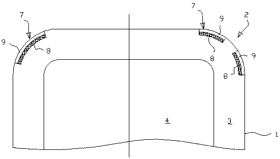
[0022] Example 2 as figure 2 As shown, the trough insulation structure is adopted. Process a groove 7 on the outer wall 1 of the crystallizer corner 2, or as figure 2 Processing several grooves 7 shown in the right part, the present embodiment preferably processes 2 grooves at most, and the depth of groove 7 on the wall thickness of the crystallizer is 1 / 4~1 / 2 of the wall thickness of the corner of the crystallizer. The mold wall thickness is 20 mm as an example, preferably 5-10 mm, and the groove 7 extends to 100-300 mm below the molten steel pouring meniscus in the length direction of the mold. The groove 7 at the corner of the crystallizer is first filled with a heat insulating material gasket 8 of a certain thickness, the heat insulating material gasket 8 is a plastic gasket or adhesive glue; The bolts are crimped on the outer wall of the crystallizer corner groove 7 . The heat insulation material is added to the corner part of the mold, which weakens the heat transfe...

Embodiment 3

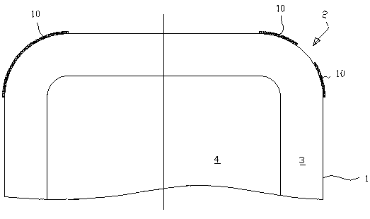
[0023] Example 3 as image 3 As shown, the coating type heat insulation structure is adopted. Spraying or bonding a layer of heat insulating material on the outer wall 1 of the crystallizer corner 2, the heat insulating material is a coating 10, or as image 3 In the spraying or bonding of two thermal insulation coatings 10 shown on the right, the thickness of the coating 10 is determined by the ratio of the material thickness of the coating 9 to the thermal conductivity. If the thickness of the coating 10 is denoted as δ1, the thermal conductivity is denoted as As λ1, the thickness of the crystallizer material is recorded as δ2, and the thermal conductivity is recorded as λ2, then the ratio of δ1 / λ1 is 10% to 30% of the ratio of the crystallizer δ2 / λ2. The thermal conductivity of the sprayed material is 25w / m.k, the coating thickness is 0.2mm, the material of the mold is copper, and its thermal conductivity is 400w / m.k, which can be estimated to be equivalent to about 20% of...


PUM

PropertyMeasurementUnit
thicknessaaaaaaaaaa

Abstract

The invention discloses a continuous casting crystallizer and particularly relates to a method for weakening corner part heat transmission of a square, rectangle or plate type continuous casting crystallizer. The method for weakening corner part heat transmission of the continuous casting crystallizer is that a thermal insulation material is added in the interior of the wall thickness of a corner material or the outer wall surface of the continuous casting crystallizer so as to weak the two-dimensional heat transfer intensity at corner parts of the continuous casting crystallizer and allow the shell of a casting blank to be solidified evenly at the corner parts and side edges of the continuous casting crystallizer; the interior of the wall thickness of the corner material of the continuous casting crystallizer refers to a range starting from the upper opening of the continuous casting crystallizer to a position 100-300 mm below a liquid steel casting meniscus. According to the invention, a deep hole type heat insulation structure, a trough-type heat insulation structure or a coating type heat insulation structure is used for weakening corner part heat transmission; the method can control the two-dimensional heat-transfer capability at corner parts of the continuous casting crystallizer, better realizes even solidification of the casting blank in the continuous casting crystallizer, and reduces the occurrence rate of corner part defects of the casting blank.

Description

technical field [0001] The invention relates to a continuous casting crystallizer, in particular to a method for weakening corner heat transfer of a square, rectangular or plate type continuous casting crystallizer. Background technique [0002] For square, rectangular or plate continuous casting molds, it is well known that the corners are two-dimensional heat transfer and cause the corners of the slab to cool more intensely than the sides, and the shells at the corners also thicken first to produce larger solids. Shrinkage, thereby exerting a tensile stress on the side slab shell, which is likely to cause defects such as surface cracks in the area near the corner of the slab side. [0003] In the prior art, Chinese patent 03262727.0 discloses a groove on the outer wall of the crystallizer and a raised structure at the corner of the outer wall of the mold. Weaken the two-dimensional heat transfer strength at the corner. This patent is theoretically the easiest to achieve ...

Claims


Application Information

Patent Timeline
Patent Type & Authority Applications(China)
IPC IPC(8): B22D11/059B22D11/057
Inventor 侯晓光胡子国
Owner BAOSHAN IRON & STEEL CO LTD
Learn More