
Self-adaptive damage compensation method and system for digital-related optical communication system

A technology of coherent optical communication and adaptive compensation, applied in baseband system components, optical fiber transmission, shaping network in transmitter/receiver, etc. Achieve the effect of occupying less spectrum resources, low computational complexity, and high compensation accuracy

Inactive Publication Date: 2013-09-18
HUAZHONG UNIV OF SCI & TECH
View PDF4 Cites 47 Cited by
  • Summary
  • Abstract
  • Description
  • Claims
  • Application Information

AI Technical Summary

Problems solved by technology

Its disadvantage is that it requires prior knowledge and is sensitive to thresholds. Improper threshold settings will seriously affect algorithm performance.
In addition, this method needs to compensate the signal dispersion first, otherwise the LFO cannot be calculated effectively
In addition, the Viterbi-Viterbi algorithm requires a large number of high-order calculations, and the amount of calculation is large, which is not conducive to reducing DSP resource occupancy and system energy consumption.
[0006] Finally, the pilot or digital auxiliary adaptive compensation algorithms proposed in the past only target a single or two kinds of impairments, and different impairments also need to be compensated based on different auxiliary signals, so they cannot satisfy the simultaneous adaptive compensation of CD, NLD, LFO and LPN , and if simply integrate several different adaptive compensation algorithms, that is, by inserting various pilots and digital auxiliary signals to realize the above functions, the system spectrum efficiency will be reduced and the transceiver structure will be more complicated.

Method used


Image

  • Self-adaptive damage compensation method and system for digital-related optical communication system
  • Self-adaptive damage compensation method and system for digital-related optical communication system
  • Self-adaptive damage compensation method and system for digital-related optical communication system

Examples


Embodiment Construction

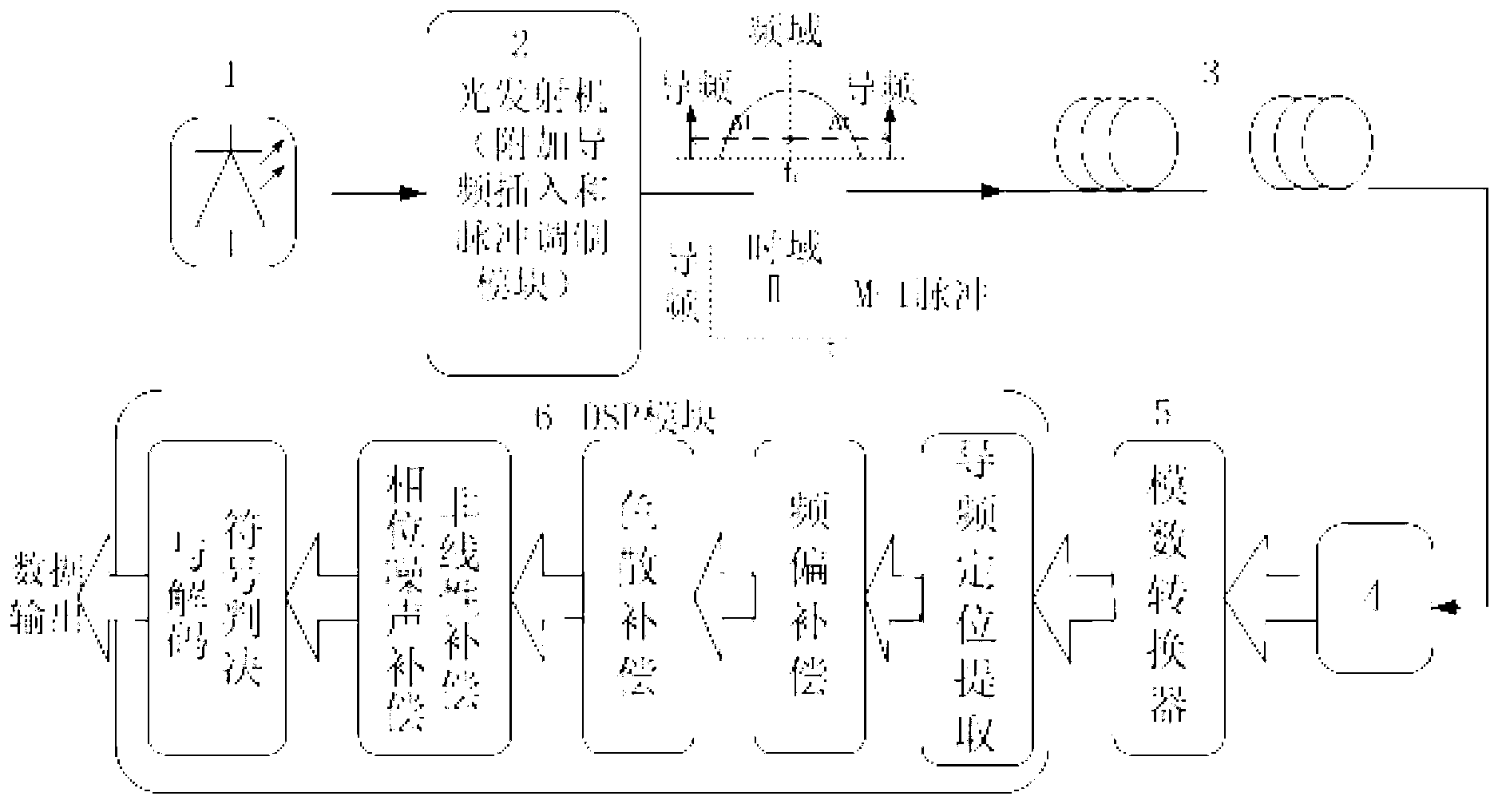
[0034] The simultaneous adaptive compensation system of CD, NLD, LFO and LPN based on the optical guide proposed by the present invention, such as figure 1 shown. It includes a pilot insertion and modulation module added to the optical transmitter 2, and an adaptive compensation module based on a digital signal processor 9 at the receiving end.

[0035] At the transmitting end: the signal light generated by the laser 1 enters the optical transmitter 2, and the optical transmitter 2 is equipped with a pilot insertion and modulation module. The pilot insertion and modulation module is used to insert two symmetrical to the signal frequency f c distributed pulse-modulated pilot signal (f c ±Δf); the optical guide and the optical signal are combined and then transmitted to the transmission optical fiber 6 .

[0036] At the receiving end: the optical receiver 7 converts the optical signal into an electrical signal output, and then enters the adaptive compensation module of the di...


PUM


Abstract

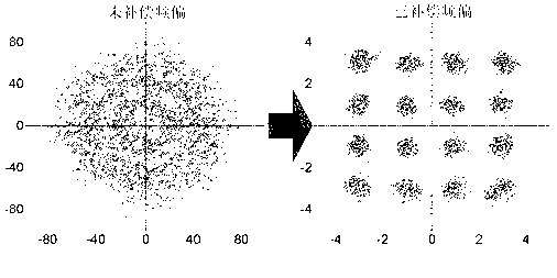
The invention relates to a self-adaptive damage compensation method and system for a digital-related optical communication system. The self-adaptive damage compensation method includes inserting two pulse modulation pilot frequency signals symmetrically distributed on an input signal frequency fc (fiber channel) at a transmitting terminal; acquiring an input signal power spectrum by the Fourier transform at a receiving terminal, and receiving the pilot frequency signals of a signal power spectrum and subjecting the pilot frequency signals to location and filtering extraction; calculating size of frequency offset of a vibration laser and performing compensation by a pilot frequency; acquiring pilot time domain waveforms by the Fourier transform and calculating a delay delta tau between two pilot light pulses, and calculating size of dispersion by the delta tau and performing the compensation; finally extracting pilot phase noises and subtracting the same from a signal phase so as to eliminate laser phase noises and nonlinear fiber damages. The self-adaptive damage compensation method has the advantages of high accuracy, low complexity, small occupation of bandwidth and fast response speed, so that self-adaptive compensation of various damages can be realized.

Description

technical field [0001] The invention relates to the technical fields of optical fiber communication, coherent detection and digital signal processing. Background technique [0002] In recent years, the combination of advanced modulation formats, coherent detection and digital signal processing techniques has greatly improved the performance of traditional WDM optical transmission systems. The advanced modulation format effectively improves the spectral efficiency of the system through multi-dimensional and multi-ary modulation of the optical signal amplitude, phase and polarization full-field information; digital coherent detection technology can convert the signal light full-field information into digital signals, compatible with various advanced Modulated format signal, with high sensitivity, and various damages to the signal through the DSP algorithm, including nonlinearity caused by chromatic dispersion (CD), phase modulation (SPM) and cross-phase modulation (XPM) in the...

Claims


Application Information

Patent Timeline
IPC IPC(8): H04L25/03H04B10/25
Inventor 崔晟方晓之徐梦然
Owner HUAZHONG UNIV OF SCI & TECH
Learn More