Factory safety management device and management method
A technology of safety management and safety processing, which is applied in the field of factory safety management devices and management, and can solve problems such as CPU load rate increase and action delay
- Summary
- Abstract
- Description
- Claims
- Application Information
AI Technical Summary
Problems solved by technology
Method used
Image
Examples
no. 1 approach
[0035] [1. Composition]
[0036] [Factory monitoring and control system]
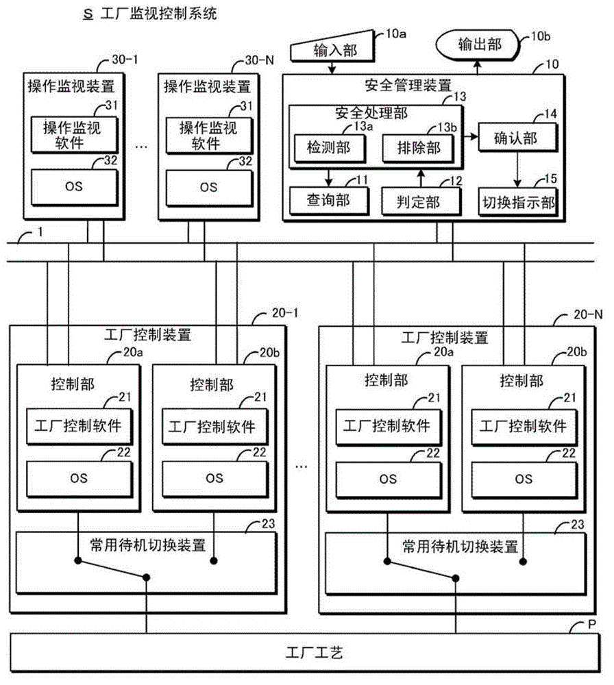
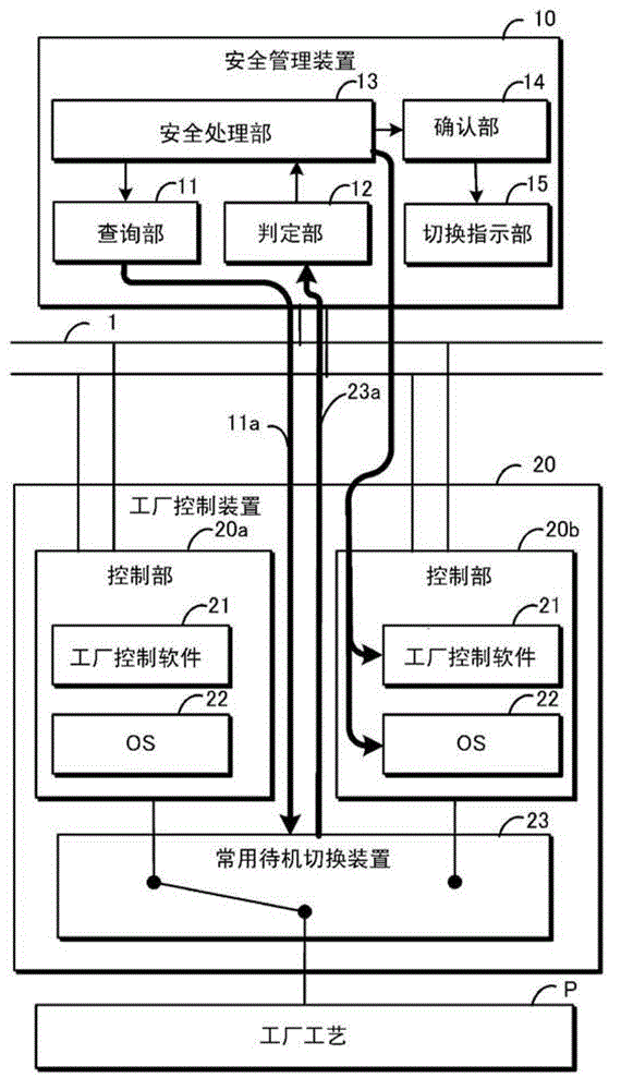
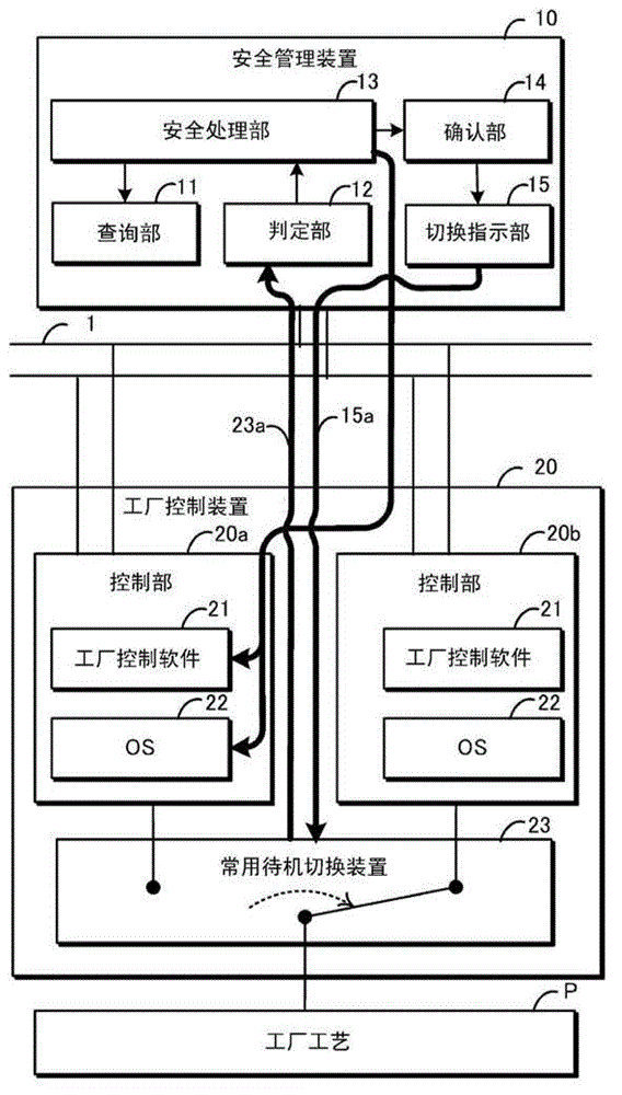
[0037] First, refer to figure 1 The factory monitoring and control system S to which the safety management device of this embodiment is applied will be described. The factory monitoring and control system S is a system for monitoring and controlling the factory process P.
[0038] Here, the factory process P is an aggregate of control elements such as various devices constituting a factory to be controlled and parameters and data indicating their operating states, and includes devices that collect, store, calculate, and output parameters and data.
[0039] Furthermore, the factory monitoring control system S includes a plurality of factory control devices 20 - 1 to 20 -N and a plurality of operation monitoring devices 30 - 1 to 30 -N as devices related to factory monitoring control. In the following description, when only the plant control device and the operation monitoring device are described, the...
no. 2 approach
[0079] [1. Composition]
[0080] refer to Figure 5 The configuration of this embodiment will be described. In addition, the same code|symbol is attached|subjected to the same structure as 1st Embodiment, and redundant description is abbreviate|omitted.
[0081] First, the load factor measurement unit 24 is provided in the control units 20 a and 20 b of the plant control device 20 . The load factor measurement unit 24 is a processing unit that measures the load factor of the CPU in the control units 20a and 20b.
[0082] Furthermore, the security management device 10 includes a load factor inquiry unit 16a, a load factor determination unit 16b, and a suppression unit 16c. The load ratio inquiry unit 16 a is a processing unit that inquires the load ratio measurement unit 24 about the load ratio. The load factor determination unit 16b is a processing unit that determines whether or not the load factor from the load factor measurement unit 24 exceeds a predetermined threshold...
no. 3 approach
[0093] [1. Composition]
[0094] refer to Figure 7The configuration of this embodiment will be described. In addition, the same code|symbol is attached|subjected to the same structure as 1st and 2nd embodiment, and redundant description is abbreviate|omitted. First, the operation monitoring device 30 has an alarm display unit 33 . The alarm display unit 33 is a processing unit that displays an alarm output from the security management device 10 . For example, the alarm display unit 33 can be constituted by an output unit of the operation monitoring device 30 .
[0095] Furthermore, the safety management device 10 has an abnormality determination unit 17a and an alarm output unit 17b. The abnormality determination unit 17 a is a processing unit that determines whether or not there is an abnormality in the result of the security processing by the security processing unit 13 . For example, when a virus is detected by the security processing unit 13, the abnormality determin...
PUM
 Abstract
Description
Claims
Application Information
 - R&D Engineer
- R&D Manager
- IP Professional
- Industry Leading Data Capabilities
- Powerful AI technology
- Patent DNA Extraction
Browse by: Latest US Patents, China's latest patents, Technical Efficacy Thesaurus, Application Domain, Technology Topic, Popular Technical Reports.
© 2024 PatSnap. All rights reserved.Legal|Privacy policy|Modern Slavery Act Transparency Statement|Sitemap|About US| Contact US: help@patsnap.com


