
Method for cutting groove of U-rib steel plate by plasma cutting torches at double variable angles for one time

A plasma, variable angle technology, applied in plasma welding equipment, welding equipment, metal processing equipment and other directions, can solve the problems of many processing procedures, poor processing quality of U-rib steel plate grooves, etc., to achieve full automation and fully automated operation , the effect of easy operation

Active Publication Date: 2013-09-18
HAIOD HEAVY ENG TECH
View PDF5 Cites 4 Cited by
  • Summary
  • Abstract
  • Description
  • Claims
  • Application Information

AI Technical Summary

Problems solved by technology

[0003] The purpose of the present invention is to solve the disadvantages of poor processing quality or many processing steps of U-ribbed steel plate grooves in the prior art, and provide a double-variable-angle plasma cutting torch that can cut U-ribbed steel plate slopes at one time with easy operation and good processing quality. Using this method, the processing process is fully automatic, which improves the efficiency of U-ribbed steel plate groove processing and ensures the quality of groove processing

Method used


Image

  • Method for cutting groove of U-rib steel plate by plasma cutting torches at double variable angles for one time

Examples


Embodiment 1

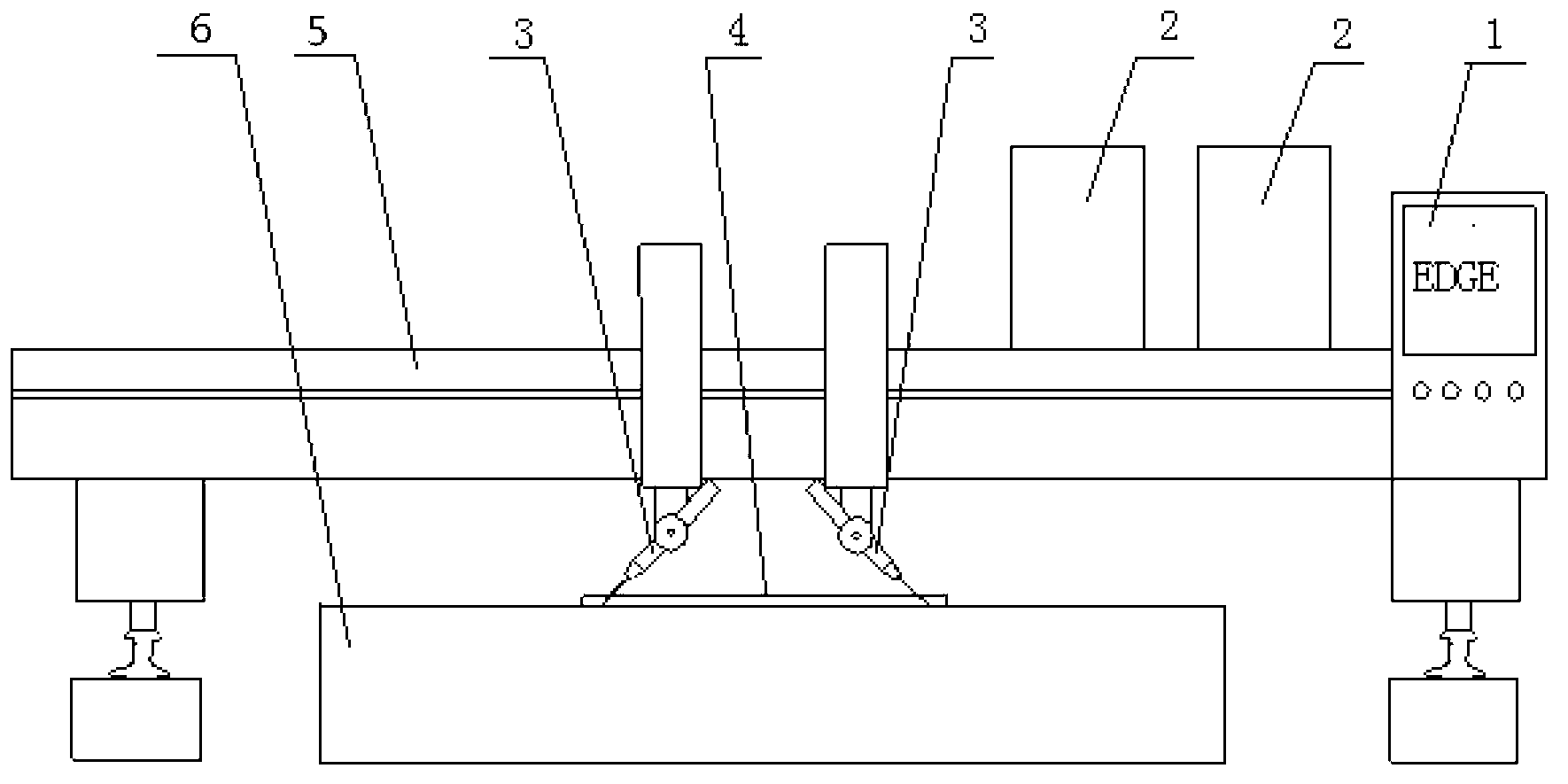
[0027] Embodiment 1: A kind of double-variable-angle plasma cutting torch provided by the present invention cuts the method of U-ribbed steel plate bevel once, operates according to the following steps:

[0028] ⑴ Choose a HPR260 plasma CNC cutting machine, such as figure 1 As shown, on the plasma CNC cutting machine body 5, two sets of max105 plasma power sources 2 and two sets of plasma cutting torches 3 that can deflect angles are installed; the two plasma cutting torches 3 are equipped with cutting torch initial height positioners , THC cutting torch arc voltage adjustment system and EDGE CNC system PLC programmable system.

[0029] (2) Fix the U-ribbed steel plate 4 to be cut on the cutting table 6 .

[0030] (3) Align the two plasma cutting torches 3 with the edge of the U rib steel plate 4 to be cut, adjust the lateral distance of the two plasma cutting torches 3, adjust the deflection angle of the two plasma cutting torches 3, and set the initial positioning of the tw...


PUM


Abstract

The invention relates to a method for cutting a groove of a U-rib steel plate by plasma cutting torches at double variable angles for one time. The method comprises steps as follows: two sets of plasma batteries and two sets of the plasma cutting torches which can deflect angles are mounted on one plasma numerical control cutting machine; the two plasma cutting torches are configured with cutting torch initial height positioners, cutting torch arc voltage adjusting systems, numerical control systems and PLC (programmable logic controller) systems; a to-be-cut steel plate is placed on a cutting table, the two plasma cutting torches are aligned to the edge of the to-be-cut steel plate, the transverse distance between the two plasma cutting torches and the angles of the two plasma cutting torches are adjusted, and initial positioning values, cutting current and cutting speeds of the two plasma cutting torches are set in the numerical control systems; and a starting button of the cutting machine is pressed, and under the control of the numerical control systems, the two plasma cutting torches simultaneously start arc and cut the U-rib steel plate. According to the method, only one processing process is required, and the U-rib steel plate can be cut for one time, therefore, the operation is simple, automatic cutting is realized, and the straightness of the cut U-rib steel plate, the surface quality of the groove and the angle accuracy all meet the design requirements.

Description

technical field [0001] The invention relates to a processing technology for U-shaped stiffening rib steel plate grooves of bridges, in particular to a method for one-time cutting of U-rib steel plate grooves by a double-variable-angle plasma cutting torch, which belongs to the field of bridge manufacturing technology. Background technique [0002] The U-shaped rib is the stiffener of the orthotropic deck of the steel bridge, and it is an important component of the bridge. The U-shaped rib plate usually used is 6-8mm thick, 300mm wide at the bottom, and about 280mm high, which is a U-shaped section. For the processing of traditional U-ribbed steel plate grooves, most enterprises adopt the process of flame cutting blanking, milling straight edges by large multi-head milling machines, and then hobbing and processing grooves by edge milling machines or chamfering machines. This type of process has many sequences, high labor costs, long processing time, and large losses. The wor...

Claims


Application Information

Patent Timeline
Patent Type & Authority Applications(China)
IPC IPC(8): B23K10/00
Inventor 宋雄文叶顺答浩陈复保
Owner HAIOD HEAVY ENG TECH
Learn More