
Integrated thoracic aortic branch support

A thoracic aorta and main stent technology, applied in the field of integrated thoracic aorta branch stents, can solve the problems of inability to use stent-grafts and stents, and achieve the effect of reducing surgical risks and medical costs, and avoiding thoracotomy

Inactive Publication Date: 2013-09-18
THE THIRD AFFILIATED HOSPITAL OF THIRD MILITARY MEDICAL UNIV OF PLA
View PDF9 Cites 3 Cited by
  • Summary
  • Abstract
  • Description
  • Claims
  • Application Information

AI Technical Summary

Problems solved by technology

[0002] With the development of interventional technology, more and more stents are used. However, due to equipment and technical reasons, stents in some special parts are still not available. For example, arterial dissections near the aortic arch cannot use stent-grafts.

Method used


Image

  • Integrated thoracic aortic branch support
  • Integrated thoracic aortic branch support
  • Integrated thoracic aortic branch support

Examples


Embodiment 1

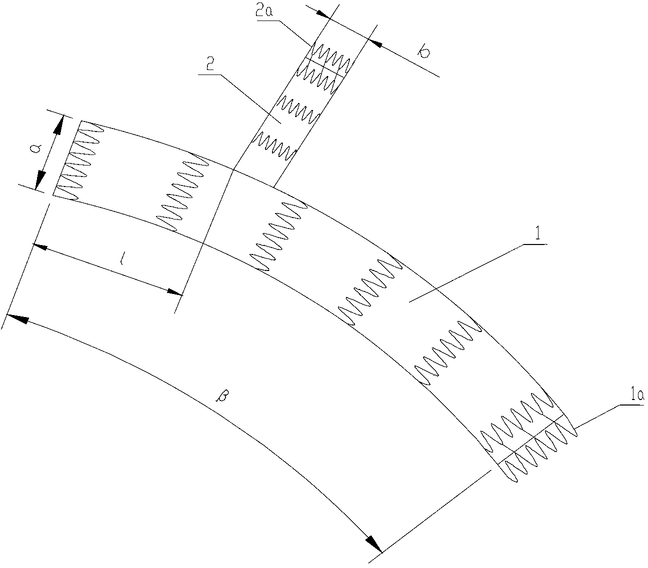
[0021] like figure 1 As shown, the integrated thoracic aortic branch stent of this embodiment includes a main stent 1 and a first sub-stent 2 arranged on the side wall of the main stent, and the main stent communicates with the first sub-stent; the main stent and the first The sub-stents are all composed of a memory alloy wire skeleton and a film fixed and covered on the skeleton. Wherein, the distance 1 between the front end of the main stent 1 and the first sub-stent 2 is 5mm-20mm; it is set to be no more than 20mm to ensure that it will not cover adjacent arteries and ensure blood supply. The diameter a of the main support 1 is 24mm-36mm; 30mm is taken in the present embodiment, and the diameter b of the first sub-support 2 is 6mm-12mm; 10mm is taken in the present embodiment, and the axis arc length of the main support 1 is 80mm-100mm; In this embodiment, 90mm is taken, and the length of the first sub-support 2 is 10mm-30mm. In this embodiment, 20 mm is used to accuratel...

Embodiment 2

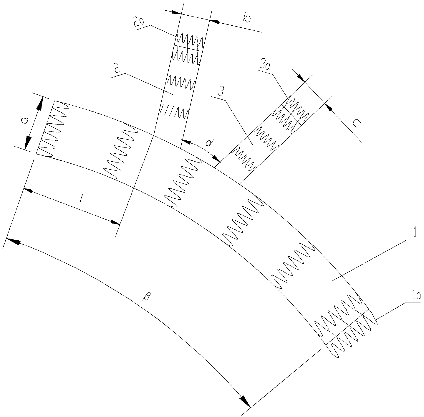
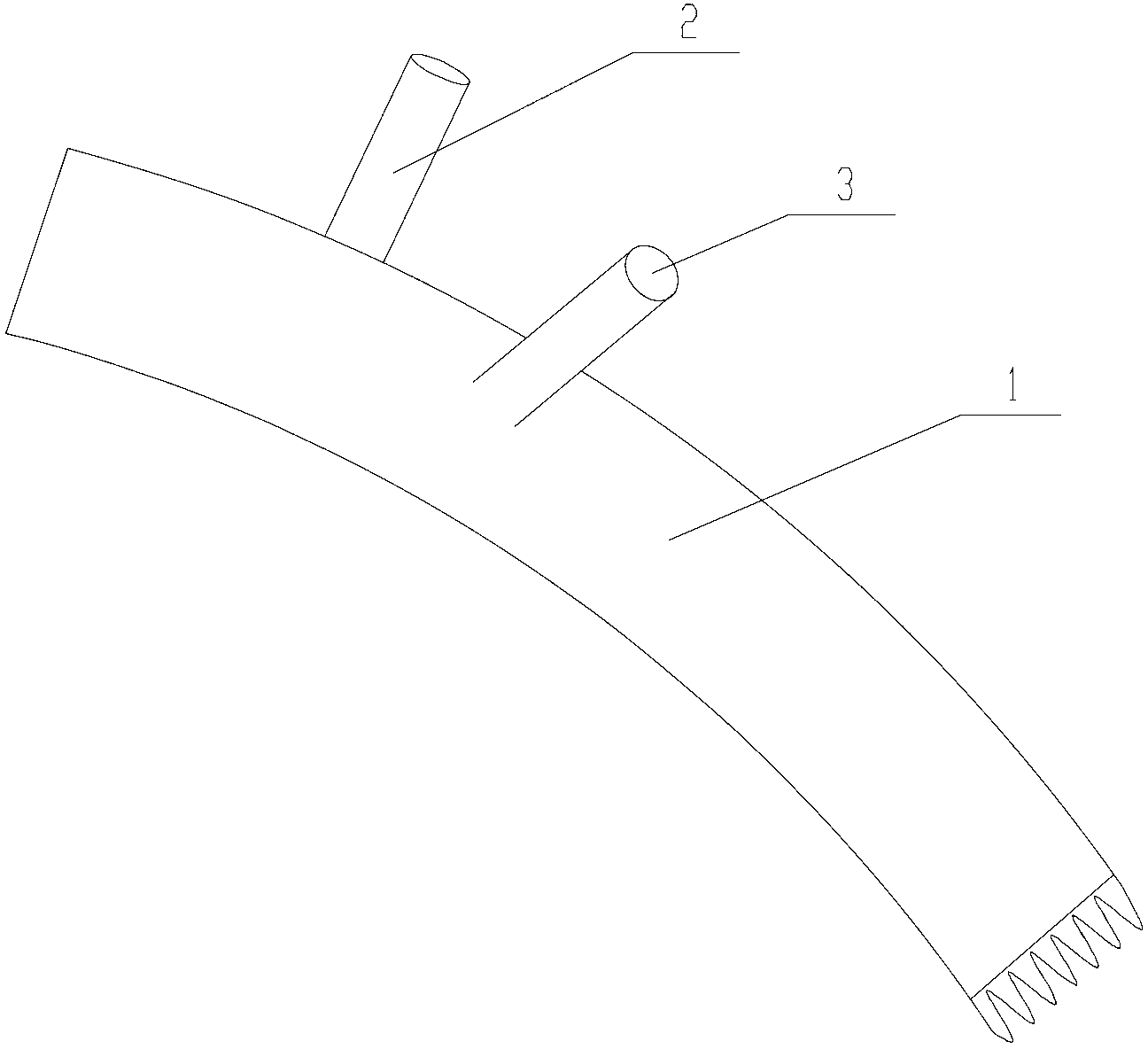
[0023] As a further improvement to Embodiment 1, it also includes a second sub-bracket 3 arranged on the side wall of the main bracket 1, and the arc length d between the first sub-bracket 2 and the second sub-bracket 3 along the main bracket 1 is 15mm- 30mm, specifically 25mm in this embodiment; the angle between the two axes of the first sub-support 2 and the second sub-support 3 is 0°-30°. Specifically take 15° in this embodiment; wherein, the diameter c of the second sub-stent 3 is 6mm-12mm, specifically 8mm in this embodiment; the length of the second sub-stent 3 is 10mm-30mm. Specifically, 20mm is taken in this embodiment; a second sub-stent is arranged on the main stent, and it is intended to reserve two most important branch artery channels when covering these important arteries, so that the thoracic main stent can reach the right brachiocephalic trunk. On the right side of the arterial opening, the first sub-stent of the main stent itself is placed in the right brachi...


PUM


Abstract

The invention relates to an integrated thoracic aortic branch support which comprises a main support and a first branch support arranged on the sidewall of the main support, wherein the main support is communicated with the first branch support; the main support and the first branch support are composed of memory alloy wire frames and tectorial membranes fixedly coating the frames. The first branch support is arranged on the main support, a most important branch artery channel is reserved when the important arteries are coated, so as to enable the thoracic aortic support to achieve the left side of the right brachiocephalic trunk opening, the first branch support carried by the main support is placed in the left common carotid artery, or conducting bridging to the right common carotid artery and the left common carotid artery, and conducting bridging to the left common carotid artery and the left subclavian artery firstly and then covering all the arcus aortas by the support, the first support is placed in the right brachiocephalic trunk, so that the support can also be used for lesion near the aortic arch, exaggerated thoracic surgery is avoided, and the surgical risk and medical cost of a patient are decreased accordingly.

Description

technical field [0001] The invention relates to the field of medical devices, in particular to an integrated thoracic aorta branch stent. Background technique [0002] With the development of interventional technology, more and more stents are used. However, due to equipment and technical reasons, stents in some special parts still cannot be used. For example, arterial dissection near the aortic arch cannot use stent-grafts. Because the stent-graft is applied to the aortic arch, it will block the head-to-head blood flow, that is, the blood flow covering the left subclavian artery, left common carotid artery, and right brachiocephalic artery trunk, resulting in cerebral ischemia, stroke, and even death. If it is necessary to cover the aortic arch with a stent-graft, at present, the right brachiocephalic trunk can only be grafted to the ascending aorta through thoracotomy, and then the right common carotid artery and the left common carotid artery are bypassed, and the left co...

Claims


Application Information

Patent Timeline
Patent Type & Authority Applications(China)
IPC IPC(8): A61F2/07
Inventor 文亚渊文译翎赵健洁张晓华陈金萍
Owner THE THIRD AFFILIATED HOSPITAL OF THIRD MILITARY MEDICAL UNIV OF PLA
Learn More