Exhaust treatment devices for diesel engines

A technology for exhaust treatment devices and diesel engines, applied to exhaust devices, engine components, machines/engines, etc., can solve problems such as not being able to fully improve PM capture efficiency

Inactive Publication Date: 2015-12-16
USUI KOKUSAI SANGYO KAISHA LTD
View PDF8 Cites 0 Cited by
  • Summary
  • Abstract
  • Description
  • Claims
  • Application Information

AI Technical Summary

Problems solved by technology

[0021] That is, in the electrical treatment method and device for diesel engine exhaust described in the aforementioned Patent Document 1, the length of the electrode needle 24 of the discharge charging part 22 in the flow direction of the exhaust gas flow is short, and the collecting plate 23 is arranged on the In the direction at right angles to the flow direction of the exhaust gas flow, in addition, since the exhaust gas flow is in direct contact with the trapping plate 23, the flow resistance (pressure loss; pressure loss) is large, and since the trapping plate 23 is thin and exhausts The length of the flow direction of the airflow is short, so there is a possibility that PM will pass through without stopping, and there is a concern that the PM collection efficiency cannot be sufficiently improved, and there is a possibility that PM that has passed through the collection plate 23 cannot pass through the corona discharge again. Instead of being charged and trapped, it is the problem of being discharged as it is

Method used


Image

  • Exhaust treatment devices for diesel engines
  • Exhaust treatment devices for diesel engines
  • Exhaust treatment devices for diesel engines

Examples


Embodiment Construction

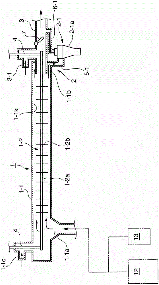
[0061] in figure 1 The exhaust gas treatment device for a large displacement diesel engine that uses low-quality fuel below heavy oil as shown in the device as the first embodiment of the present invention is roughly divided and includes a tubular collection part 1 constituting an electric dust collection mechanism And the separation and collection unit 2 constituting the separation and collection mechanism, and the tubular collection unit 1 provided to collect PM particles is equipped with a collection tube 1-having a predetermined length and a collection wall surface 1-1k constituting a dust collecting electrode. 1. And discharge electrodes 1-2 that charge PM contained in exhaust gas. On the collecting pipe 1-1 constituting the dust collecting electrode, there is an exhaust gas inlet 1-1a at the end of the upstream side (diesel engine side), and the PM low concentration exhaust is connected and installed near the axis of the downstream end. The gas outlet pipe 3 is connected...


PUM


Abstract

The present invention provides an exhaust gas purification device for a large-displacement diesel engine using low-quality fuel below heavy oil and achieving miniaturization of a cyclone separator, high PM collection rate, and low fuel consumption. Exhaust treatment device for a large-displacement diesel engine using low-quality fuel below heavy oil has a discharge electrode for charging particulate matter contained in exhaust gas of a large-displacement diesel engine using low-quality fuel below heavy oil , and the tubular collecting part that constitutes the dust-collecting electrode that collects the charged particulate matter, and is equipped with a cyclone-type separating and collecting mechanism that separates and collects the granular matter peeled off from the tubular collecting part, and is characterized in that A cyclone separator collection mechanism consisting of one or more tangential cyclone separators is equipped in the high-concentration exhaust gas outlet of the particulate matter near the inner surface of the downstream side of the tubular collection part, and the high-concentration exhaust gas The high-concentration exhaust gas flow discharged from the lead-out unit is selectively introduced into the tangential cyclone separator according to the flow rate of the exhaust gas.

Description

Technical field [0001] The present invention relates to a ship that removes and purifies particulate matter (ParticulateMatter: hereinafter referred to as "PM") and harmful gases mainly containing carbon contained in the exhaust gas of a large displacement diesel engine using low-quality fuel below heavy oil Exhaust gas treatment technology for large displacement diesel engines that use low-quality fuels below heavy oil, for power generation, industrial use, etc., more specifically, it relates to the use of exhaust gas that emits high-temperature exhaust gas below heavy oil A corona discharge exhaust treatment device in a large displacement diesel engine with low quality fuel. Background technique [0002] Diesel engines are widely used as power sources for various ships, engines, large construction machinery, and various automobiles. However, PM contained in the exhaust gas discharged from the diesel engine not only causes well-known air pollution, but also It is extremely harm...

Claims


Application Information

Patent Timeline
Patent Type & Authority Patents(China)
IPC IPC(8): F01N3/02B03C3/15B03C3/40B03C3/41B03C3/49B04C5/04
CPCB03C3/15B03C3/368B03C3/41B03C3/49B03C3/86B03C2201/08B03C2201/10B03C2201/30B04C2009/001F01N3/01F01N3/027F01N3/0275F01N3/037B03C3/40B04C5/04F01N3/02
Inventor 古坚宗胜牧野义泷川一仪
Owner USUI KOKUSAI SANGYO KAISHA LTD
Why Eureka
Try Eureka