A Method of Improving Scanning Linearity of Signal Analyzer
A signal analyzer, scanning linear technology, applied in spectrum analysis/Fourier analysis, automatic power control, electrical components, etc., can solve problems such as tuning voltage nonlinearity, control voltage oscillation amplitude becoming large, and reducing scanning speed
- Summary
- Abstract
- Description
- Claims
- Application Information
AI Technical Summary
Problems solved by technology
Method used
Image
Examples
Embodiment 1
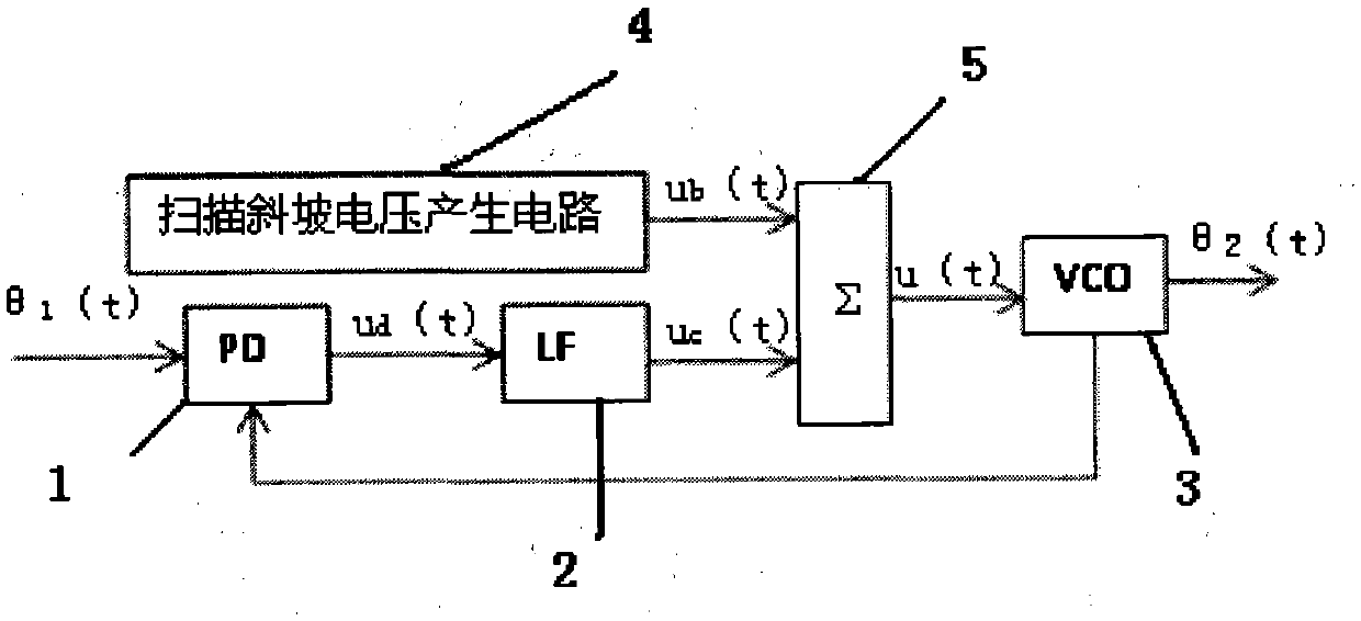
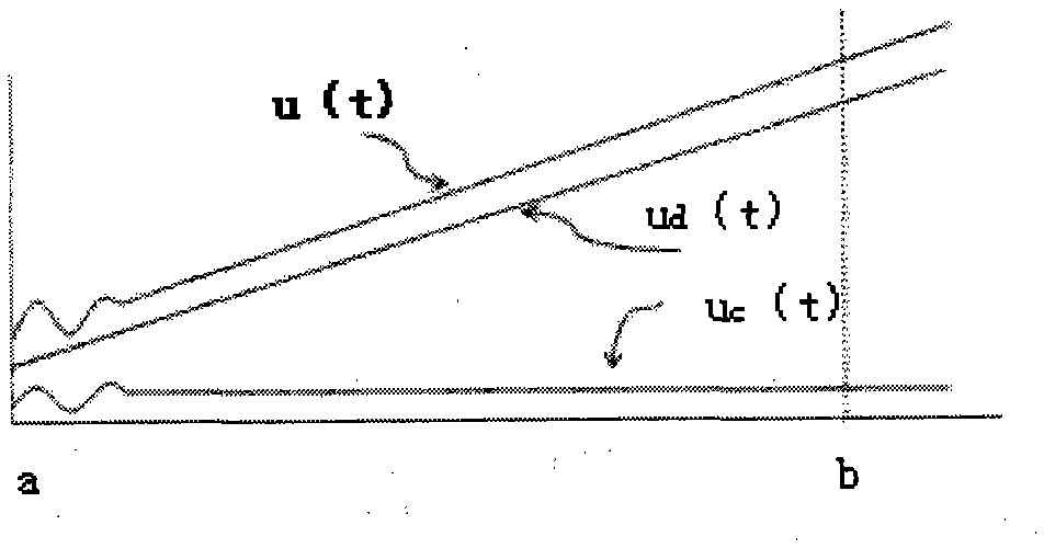
[0028] The invention provides a method for improving the scanning linearity of a signal analyzer, such as Figure 4 As shown, the signal under test is input into the mixer 102 through the preselection filter 101 , and the intermediate frequency signal mixed with the sweeping local oscillator 103 passes through the resolution bandwidth filter 104 and enters the detector 105 to obtain the signal amplitude 107 . Such as Figure 4 As shown, assuming that the scan time is T, when performing a sweep measurement, take the measurement of the spectrum of frequency bands a to b as an example, here it is assumed that the local oscillator starts scanning at time T0, and the scanning driver 106 drives the local oscillator 103 to start scanning; when time T1 , the scanning driver 106 drives the local oscillator 103 to start linear scanning, and at the same time drives the detector 105 to start the detection operation, the frequency of the local oscillator is continuously tuned from a, and t...
Embodiment 2
[0040] On the basis of the above examples, if Figure 4-Figure 5 As shown, the present invention provides a kind of method for improving the scanning linearity of signal analyzer, which comprises the following steps:
[0041] Step A: recalculate the start frequency c of the local oscillator pre-scan according to the start and end frequency points and speed of the scan, c=a-[(b-a)K / T]; wherein the measured frequency band is the frequency spectrum of a to b frequency bands;
[0042] Step B: Set the initial frequency point c and scanning speed (b-a) / T of the local oscillator pre-scan;
[0043] Step C: set to control the scanning ramp driver to drive the local oscillator to start scanning at time T0; where time T0 is the time corresponding to pre-scanning point c;
[0044] Step D: Delay and wait until the time T1 arrives, the waiting time is the duration K of the oscillation of the control voltage uc(t);
[0045] Step E: During the time period of T2-T1, the data output by the dete...
PUM
 Abstract
Description
Claims
Application Information
 - R&D
- Intellectual Property
- Life Sciences
- Materials
- Tech Scout
- Unparalleled Data Quality
- Higher Quality Content
- 60% Fewer Hallucinations
Browse by: Latest US Patents, China's latest patents, Technical Efficacy Thesaurus, Application Domain, Technology Topic, Popular Technical Reports.
© 2025 PatSnap. All rights reserved.Legal|Privacy policy|Modern Slavery Act Transparency Statement|Sitemap|About US| Contact US: help@patsnap.com


